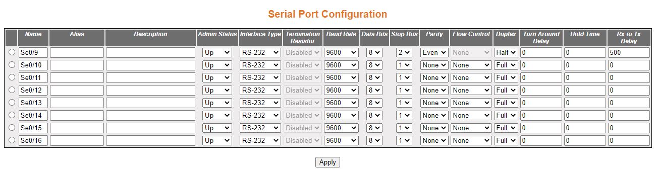
| Screen Objective |
This screen allows the user to configure the Serial
Port Configuration. |
| Navigation |
|
| Name |
Select a serial port.
|
| Alias |
Describe the ifAlias for the interface of
the serial port. This is a string with a maximum of 63 characters.
|
| Description |
Enter the description of the serial port.
This is a string with a maximum of 27 characters.
|
| Admin Status |
- Up—select for
the interface to be up.
- Down—select for the interface to be shut down.
|
| Interface Type |
- RS-232—enter this option for RS-232 interface. This is default.
Use this option for full duplex, maximum distance of 15 meters at
9600 bps, contacts such as TxD, RxD, RTS, CTS, DTR, DSR, DCD, GND, point-to-point topology, and
1 connected device
- RS-422—enter this option for RS-422.
Use this option for full duplex, maximum distance of 1200 meters
at 9600 bps, 4 wires with contacts such as TxA, TxB, RxA, RxB and
a common GND wire, point-to-point
topology, and 1 transmitting device (with 10 devices in receive
mode).
- RS-485-2—enter this option for RS-485 (2
wires). Use this option for multipoint topology or maximum number
of 32 connected devices (with the help of additional repeaters and
signal amplifiers up to 256 devices). Other characteristics are
half duplex, maximum distance of 1200 meters at 9600 bps and contacts such
as DataA, DataB, and GND.
- RS-485-4—this option for RS-485 (4
wires). Use this option for multipoint topology or maximum number
of 32 connected devices (with the help of additional repeaters and
signal amplifiers up to 256 devices). Other characteristics are
full duplex, maximum distance of 1200 meters at 9600 bps and contacts such
as DataA, DataB, and GND.
|
| Termination Resistor |
Specify the status of the termination resistor.
The options are:
- Disabled—enter
this option to disable the termination resistor. This is default.
- Enabled—enter this option to enable the
termination resistor. A special 120-ohm termination resistor can
be used to prevent reflection of the signal from the end of the
line for interface with 1200 meters distance between the receiver
and the transmitter. For RS-422,
the resistor is set between RX +
and RX-contacts at the beginning
and end of the line.
Note: This field can be configured
only for RS-422 and RS-485 interfaces.
|
| Baud Rate |
Select a number that represent the baud-rate
setting. The available values are:
- 115200 baudrate of
115200 bps
- 1200 baudrate of 1200 bps
- 14400 baudrate of 14400 bps
- 19200 baudrate of 19200 bps
- 230400 baudrate of 230400 bps
- 2400 baudrate of 2400 bps
- 38400 baudrate of 38400 bps
- 4800 baudrate of 4800 bps
- 57600 baudrate of 57600 bps
- 9600 baudrate of 9600 bps - this is the default option
|
| Data Bits |
Select the number of bits for the port to
operate with. The available values are:
- 8—this
is default. Binary data is typically transmitted as eight bits.
- 7—text-based data is transmitted as seven bits or eight
bits. If the data is based on the ASCII character set, then a minimum
of seven bits is required because there are 27 or 128 distinct characters.
If an eighth bit is used, it must have a value of 0
|
| Stop Bits |
Select the number of stop bits to signal
the end of a serial frame or packet. The available values are:
- 1—this is default. Choose 1 stop bit if parity is used.
- 2—choose 2 stop bits with no parity.
|
| Parity |
Select a number for parity. When parity
is used with a serial port, an extra data bit is sent with each
data character and is arranged so that the number of 1 bits in each character,
including the parity bit, is always odd or always even. If a byte
is received with the wrong number of 1s, then, it must have been
corrupted. However, an even number of errors can pass the parity
check. The available options are:
- None—this is
default. Select this option for no error checking mechanism.
- Odd—select this option for the number of 1's in the data
plus parity to be an even number.
- Even—select this option for the number of 1's
in the data plus parity to be an odd number.
|
| Flow Control |
Select a method of flow control. Flow control
provides extra signaling to inform the transmitter that it should
stop (pause) or start (resume) the transmission. There is a hardware
and software flow control. The available options are:
- None—this
is default. Select this option for no error checking mechanism.
- Hardware—select this option for the hardware flow control.
For RS-232, the hardware method
uses the RTS/ CTS outputs. If the transmitter
is ready to send data, then it sets the signal on the RTS line. If the receiver is ready
to receive data, it sets the signal on the CTS line.
If one of the signals is not set, no data transfer will occur.
- Software —select this option for the software flow control.The
software method uses the Xon and Xoff characters (in the ASCII characters
set: Xon = 17, Xoff = 19) which are transmitted using the same TXD
/ RXD communication lines as the main data instead of the pins.
If the data cannot be received, the receiver transmits the Xoff
symbol. To resume data transmission, the Xon symbol is sent.
|
| Duplex |
Select the number of enable half duplex
or full duplex speed. The options are:
- Full—this
is default. Use this option when data can be received and transmitted simultaneously.
- Half—choose this option for half duplex. Half duplex
is to be used while the interface is either transmit ting or receiving.
|
| Turn Around Delay |
Enter a number for the turn around delay.
This is the amount of delay inserted between the transmission of
individual messages on a serial port. It represents the delay between
sending a message and the next poll out of the serial port. Some devices
does not respond to specific message like broadcast; in that case,
enough time must be ensured for processing. This an integer in the
range of 0 to 1000 ms with a default of 0 ms.
|
| Hold Time |
Enter a a value, in milliseconds, for the
delay time after which UART start
listening to Rx line. This an integer in the range of 0 to 15000
ms with a default of 0 ms. Hold time is the maximum amount of time
that the serial packet can be held in the queue before being sent
to the serial line.
|
| Rx to Tx Delay |
Enter a number for the Rx to Tx Delay. This
is the delay between Receive mode and Transmit mode. This an integer
in the range of 0 to 1000 ms.
|
| Buttons |
- Apply—modifies
attributes and saves the changes.
|