| Part # | Slots 1-4 Line Module Description | |
|---|---|---|
| BLK | Blank Module | |
| 4DB09 | 4 x Serial DB09 Interfaces, RS 232/422/485 | |
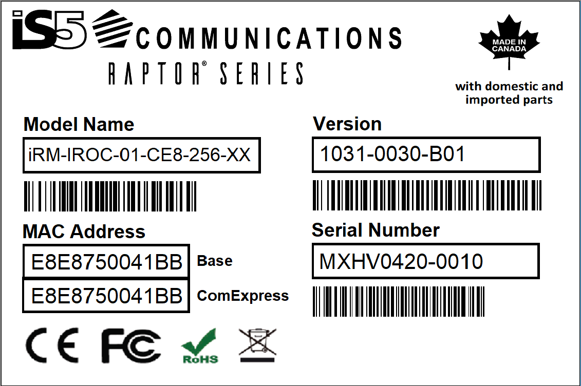
| IROC | Industrial Computing Module is in itself a configurable
part and will be described further in its own section of the manual
along with its configurable options. Only two iROCs may be installed
in the RAPTOR at a time.
Storage on the iROC is available
as either 256 GB, 512 GB, 1 TB, or 2 TB SSD with
3K P/E (Program/Erase) cycles.
The SSDs are industrial grade
rated for a temperature range of -40°C to +85°C. They provide an
SATA III 6 Gbps interface.
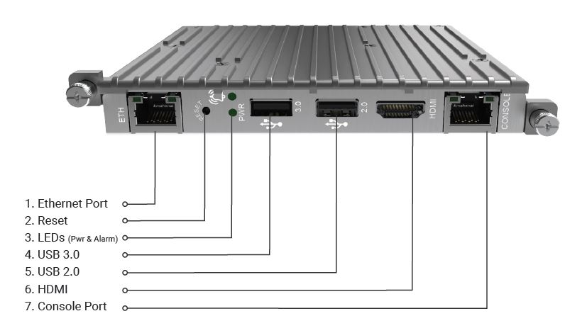
The CPU is an Intel 3950, 4-core, 4-threads, 1.6GHz, and with 8GB LPDDR4 memory. The faceplate has a 1 Gbps network interface, HDMI port capable of 1080p, USB 2.0, USB 3.0 and RJ45 RS232 Console port. There is a reset button and two LEDs (Power and Alarm). |
| Part # | Slots 1 - 3 Line Modules Description | |
|---|---|---|
| 8GRJ45 | 8 X 10/100/1000Base-T(X) RJ45 | |
| 8GRJ45P | 8 X 10/100/1000Base-T(X) RJ45, Power over Ethernet ( PoE) capable. Operating temperature is restricted to -40°C to +75°C. | |
| 8GSFP | 8 X 100/1000Base-X SFP (optical transceivers are not included) | |
| 4RJ4SFP | 4 X 10/100/1000Base-T(X) RJ45 plus 4 X 100/1000Base-X SFP (optical transceivers are not included) |
| Part # | Slot 4 Line Module Description | |
|---|---|---|
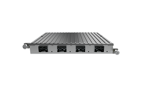
| 4TGSFP | 4 X 1G/10GBase-X SFP (optical transceivers are not included) |
| Part # | Description | Nominal Range/ Operating Range |
|---|---|---|
| LV | Low Voltage Power Module | 24 VDC, 2.5 A, 60 W / 10-36 VDC |
| MV | Medium Voltage Power Module | 48 VDC, 1.25 A, 60 W / 36-72 VDC |
| HV | High Voltage Power Module | 100-240 VAC, 50/60 Hz, 1 A, 60 VA; 100-240 VDC, 1A, 60W / 85-264 VAC; 88-300 VDC |
| HV2 | High Voltage Power Module | 100-240 VAC, 50/60 Hz, 1 A, 60 VA; 100-240 VDC, 1A, 60W / 85-264 VAC; 88-300 VDC |
Line Modules Details
The line modules ( LM) are as shown below:
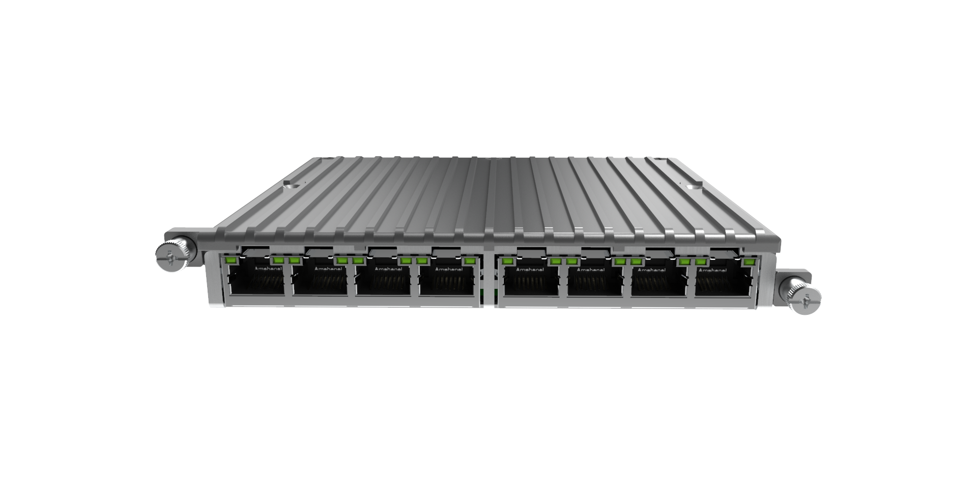
iRM-8GRJ45 - 8 x 10/100/1000 Base -T(X) RJ45 (to be used in Slots 1, 2, and 3)
Both the right and left LEDs for each port behave identically. The green LED will be in an ON state when the link is up, and will flash when there is network activity. The LED will be OFF when the link is down.
iRM-8GRJ45P - 8 x 10/100/1000 Base -T(X) RJ45 (to be used in Slots 1, 2, and 3)
Both the right and left LEDs for each port behave identically. The green LED will be in an ON state when the link is up, and will flash when there is network activity. The LED will be OFF when the link is down.
Operating temperature is restricted to -40°C to +75°C
iRM-8GSFP - 8 x 100/1000Base-X SFP (to be used in Slots 1, 2, and 3)
The green LED for each port will be in an ON state when the link is up, and will flash when there is network activity. The LED will be OFF when the link is down.
iRM-2RBX - Support for 2 RedBoxes or 1 QuadBox (supported in slots 1-4)
The numbering convention for the different RedBoxes in the different line module slots are as follows:| Redundant Switch | LM1 | LM2 | LM3 | LM4 |
|---|---|---|---|---|
| First | Red 1 | Red 3 | Red 5 | Red 7 |
| Second | Red 2 | Red 4 | Red 6 | Red 8 |
By default, both redundant switches of the HSR-PRP line card are connected to the main switch through the I-port. However, there may be cases when only one or no redundant switch is required. For these cases it is possible to disable redundancy on a redundant interface so that two Ethernet ports can be used instead, thereby by-passing the redundant switch.
Only half of the possible line card ports are routed to the HSR-PRP line card. It is therefore only possible to get four Ethernet ports to the connectors (or two 1G Ethernet ports in the case of LM4 as HSR-PRP line card does not support 10G). The following port combinations can be achieved for the four different slots:
| LM1 Line Card | HSR-PRP | 8GRJ45 | |||
|---|---|---|---|---|---|
| Red 1 Redundancy | Enable | Enable | Disable | Disable | - |
| Red 2 Redundancy | Enable | Disable | Enable | Disable | - |
| Port 1 | Red 1A | Red 1A | Gi 0/1 | Gi 0/1 | Gi 0/1 |
| Port 2 | Red 1B | Red 1B | Gi 0/2 | Gi 0/2 | Gi 0/2 |
| Port 3 | Red 2A | Gi 0/3 | Red 2A | Gi 0/3 | Gi 0/3 |
| Port 4 | Red 2B | Gi 0/4 | Red 2B | Gi 0/4 | Gi 0/4 |
| Port 5 | - | - | - | - | Gi 0/5 |
| Port 6 | - | - | - | - | Gi 0/6 |
| Port 7 | - | - | - | - | Gi 0/7 |
| Port 8 | - | - | - | - | Gi 0/8 |
| LM2 Line Card | HSR-PRP | 8GRJ45 | |||
|---|---|---|---|---|---|
| Red 3 Redundancy | Enable | Enable | Disable | Disable | - |
| Red 4 Redundancy | Enable | Disable | Enable | Disable | - |
| Port 1 | Red 3A | Red 3A | Gi 0/9 | Gi 0/9 | Gi 0/9 |
| Port 2 | Red 3B | Red 3B | Gi 0/10 | Gi 0/10 | Gi 0/10 |
| Port 3 | Red 4A | Gi 0/11 | Red 4A | Gi 0/11 | Gi 0/11 |
| Port 4 | Red 4B | Gi 0/12 | Red 4B | Gi 0/12 | Gi 0/12 |
| Port 5 | - | - | - | - | Gi 0/13 |
| Port 6 | - | - | - | - | Gi 0/14 |
| Port 7 | - | - | - | - | Gi 0/15 |
| Port 8 | - | - | - | - | Gi 0/16 |
| LM3 Line Card | HSR-PRP | 8GRJ45 | |||
|---|---|---|---|---|---|
| Red 5 Redundancy | Enable | Enable | Disable | Disable | - |
| Red 6 Redundancy | Enable | Disable | Enable | Disable | - |
| Port 1 | Red 5A | Red 5A | Gi 0/17 | Gi 0/17 | Gi 0/17 |
| Port 2 | Red 5B | Red 5B | Gi 0/18 | Gi 0/18 | Gi 0/18 |
| Port 3 | Red 6A | Gi 0/19 | Red 6A | Gi 0/19 | Gi 0/19 |
| Port 4 | Red 6B | Gi 0/20 | Red 6B | Gi 0/20 | Gi 0/20 |
| Port 5 | - | - | - | - | Gi 0/21 |
| Port 6 | - | - | - | - | Gi 0/22 |
| Port 7 | - | - | - | - | Gi 0/23 |
| Port 8 | - | - | - | - | Gi 0/24 |
| LM4 Line Card | HSR-PRP | 4TGSFP | |||
|---|---|---|---|---|---|
| Red 7 Redundancy | Enable | Enable | Disable | Disable | - |
| Red 8 Redundancy | Enable | Disable | Enable | Disable | - |
| Port 1 | Red 7A | Red 7A | Ex 0/1 | Ex 0/1 (1G) | Ex 0/1 |
| Port 2 | Red 7B | Red 7B | - | - | Ex 0/2 |
| Port 3 | Red 8A | Ex 0/3 (1G) | Red 8A | Ex 0/3 (1G) | Ex 0/3 |
| Port 4 | Red 8B | - | Red 8B | - | Ex 0/4 |
The HSR-PRP line card has four combo ports consisting of four RJ45 and four SFP interfaces.
Each combo port has one RJ45 and one SFP interface. If an SFP module is detected, the SFP interface is the active combo port interface. If there is no SFP module inserted then the RJ45 interface remains active.The IEC 62439-3 HSR-PRP standard also requires that Port-A is to the left of Port-B (Raptor) (or above in the case of MicroRaptor). With the line card being flipped up-side-down between odd and even slots the HSR-PRP line card could have either four RJ45 interfaces followed by four SFP slots or the other way round. To locate the correct interface, information can be obtained through the front-panel LCD:

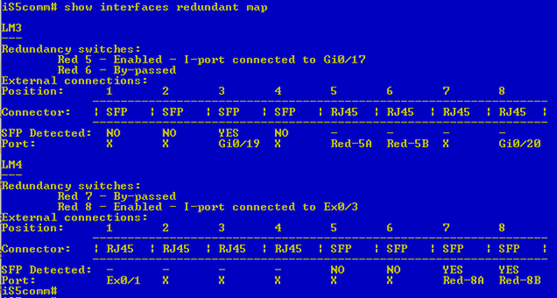
The CLI provides a redundancy map to indicate the active ports on the HSR/PRP module as well:
_LM_Rendering(front-angle).png)
iRM-4RJ4SFP - 8 x 10/100/1000 Base -T(X) RJ45 plus 4 x 100/1000Base-X SFP (to be used in Slots 1, 2, and 3)
The green LEDs for each port will be in an ON state when the link is up, and will flash when there is network activity. The LEDs will be OFF when the link is down.
iRM-8SRJ45 - 8-port RJ45 RS232/422/485 (slots 1-4)

iRM-4DB09 - 4-port DB09 RS232/422/485 (slots 1-4)

| Option | Order Code | Description |
|---|---|---|
| Model | iRM-iROC | iROC Computing Module, HDMI version 1.4 port supporting 1080p, USB 2.0 Port, USB 3.0 Port, RS 232 Console Port, 10/100/1000TX RJ45 Ethernet Port |
| CPU and Memory | 01 | Intel E3940, 4-core, 4-threads, 1.6 GHz, with 8GB LPDDR4 Memory. |
| Operating System | W10 | Windows 10 Professional |
| CE8 | Linux CentOS 8.2 | |
| Storage | 256 | 256 GB SSD with an operating temperature range of -40°C to +70°C. It has a SATA III 6 Gbps interface and 3K P/E cycles. |
| 512 | 512 GB SSD with an operating temperature range of -40°C to +70°C. It has a SATA III 6Gbps interface and 3K P/E cycles. | |
| 1TB | 1 TB Industrial SSD Storage temperature range of -40°C to +70°C. It has a SATA III 6Gbps interface and 3K P/E cycles. |
|
| 2TB | 2 TB Industrial SSD Storage temperature range of -40°C to +70°C. It has a SATA III 6Gbps interface and 3K P/E cycles. |
|
| Module Notes | The LEDs on the console port of the iROC are nonoperational at this time. Note that the USB can supply up to a maximum of 500 mA. |
iROC Network Interfaces on the iMX950
The following table describes the iROCs Ethernet connections and how they appear in CentOS.
| Connection | CentOS | Windows |
|---|---|---|
| Front-panel RJ45 Ethernet | Shows up as enp4s0 | Shows up as Ethernet 4 (Intel(R) I211 Gigabit Network Connection) |
| Front-panel Console Port | RS232 Port that is managed by operating system and can be used in different ways. | RS232 Port that is managed by operating system and can be used in different ways. |
| Back-plane Ethernet connection 1 | Shows up as enp1s0 | Shows up as Ethernet 5(Intel(R) I210 Gigabit Backplane Connection) |
| Back-plane Ethernet connection 2 | Shows up as enp2s0 | Shows up as Ethernet 6(Intel(R) I210 Gigabit Backplane Connection) |
| Back-plane Ethernet connection 3 | Shows up as enp3s0 (only available in LM4) | Shows up as Ethernet 7 (Intel(R) I210 Gigabit Backplane Connection) (only available in LM4) |
This table describes how the iROC backplane connections are mapped to the switch.
| iROC Slot Location | enp1s0/Ethernet 5 | enp2s0/Ethernet 6 | enp3s0/Ethernet 7 |
|---|---|---|---|
| LM1 | Gi0/1 | Gi0/5 | |
| LM2 | Gi0/9 | Gi0/13 | |
| LM3 | Gi0/17 | Gi0/21 | |
| LM4 | Ex0/1 | Ex0/3 | Ex0/4 |
