iMR920 supports up to one HV power supply or dual DC power supplies. The connections for the power supply are located on the terminal block.
iMR920 supports up to one HV power supply or dual DC power supplies. The connections for the power supply are located on the terminal block.
Hi-Pot Testing is a dielectric test meant to ensure that no current will flow from one point to another point. This test necessarily involves high voltages and must only be performed by qualified electrical engineers and technicians.

The following instructions apply to High Voltage Power Supplies
Hi-Pot testing on the High Voltage Power supply is complete.
Hi-Pot Testing is a dielectric test meant to ensure that no current will flow from one point to another point. This test necessarily involves high voltages and must only be performed by qualified electrical engineers and technicians.
The following instructions apply to Medium Voltage Power Supplies
Hi-Pot testing on the Medium Voltage Power supply is complete.
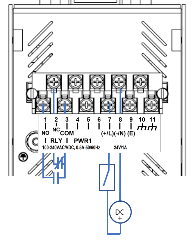
The relay contact of the terminal block connector is used to detect user-configured events. The switch provides fail open and fail close contacts to form relay circuits based on requirements. If the device is not powered, or if an active alarm is present, the relay de-energizes, therefore initiating the NO and NC states. The contacts are energized upon power up of the unit and remain energized unless a critical error occurs. One common application for this output is to raise an alarm if a power failure or removal of control power occurs.
| Event | NO (Normally Open) | NC (Normally Closed) |
|---|---|---|
| No Alarm | Closed | Open |
| Alarm Present | Open | Closed |
All equipment must be installed according to applicable local wiring codes and standards.
Always use cables that are rated for the operating ambient temperature of 85°C.
For 100-240 VAC rated equipment, protection for earth fault is provided by max. 20 A branch circuit from AC input in building installation. The protection in the building installation is relied upon for short-circuit backup protection.
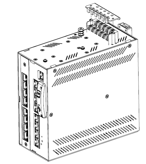
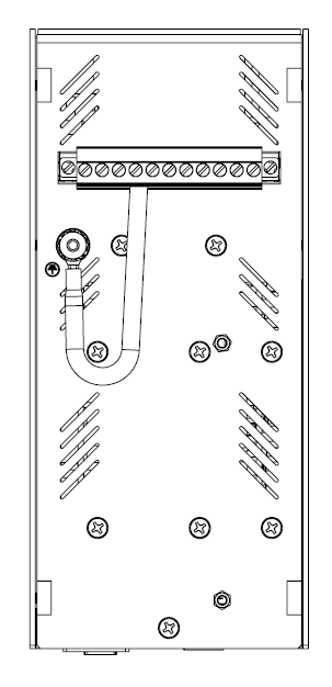
Before attaching wires to the lug type terminal block remove the protector cover, shown in Figure 1. Re-attach the cover once the wires have been screwed in place.
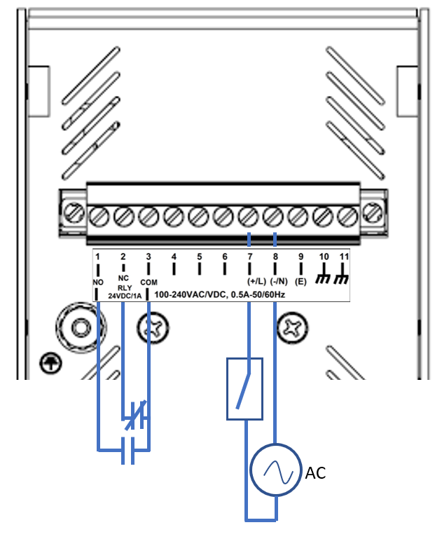

To establish AC power connection with the power source turned off, follow the steps below. When following the instructions, refer to Figure 2.
To keep the wires from pulling loose, use a small flat-blade screwdriver to tighten the wire-clamp screws on the front of the terminal block connector.

Equipment must be installed according to applicable local wiring codes and standards.
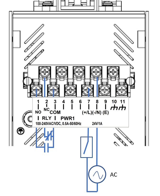
With the power source turned off, refer to figure Figure 4 and perform the following steps:
For a DC Power Supply, carry out steps 1 through 2.
After wiring is completed, perform the following:

Equipment must be installed according to applicable local wiring codes and standards.
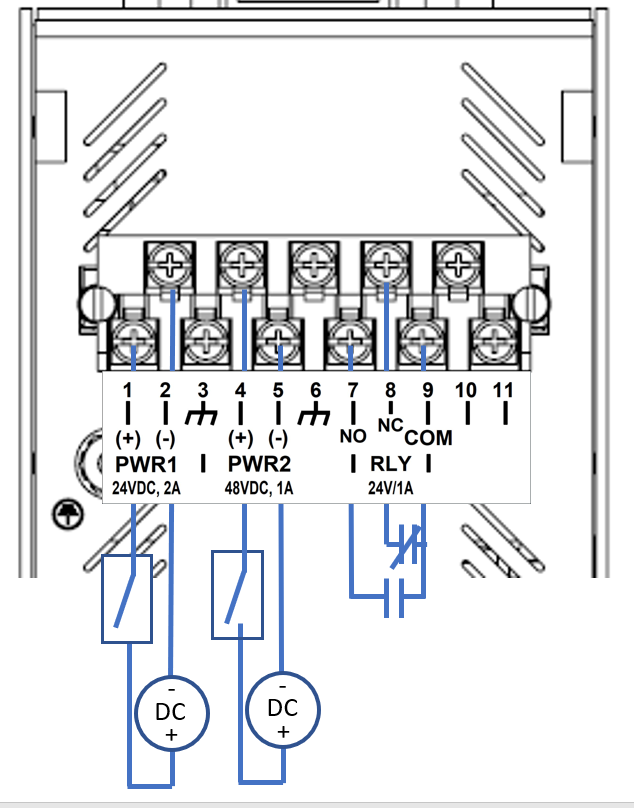
With the power source turned off, refer to figure Figure 6 and perform the following steps:
For a DC Power Supply in PS1, carry out steps 1 through 2.
If a DC Power Supply has been installed in PS2, perform the following steps.
After wiring is completed, perform the following:
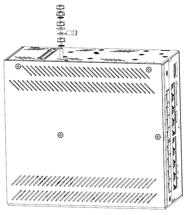

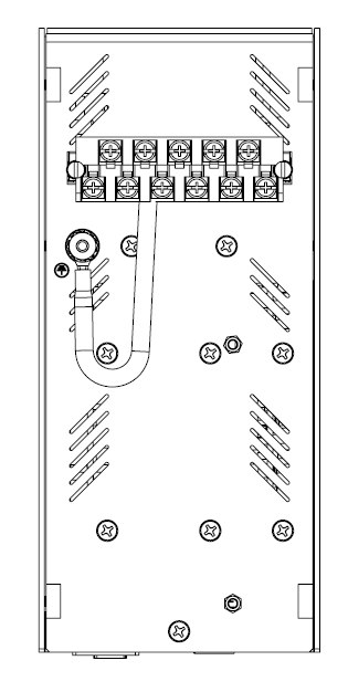

iS5 recommends using the strain relief clips provided.
The cable will not be hanging freely from the terminal block, instead it will be more securely attached to the iMR920.
Periodically inspect the clips for signs of wear. Replace if they are showing cracks or becoming brittle with age.