The iMR350 has two terminal blocks. One serves to connect the HV power supplies, the other supports the LV, and MV options. This section documents how to safely connect a power source to the iMR350.


The iMR350 has two terminal blocks. One serves to connect the HV power supplies, the other supports the LV, and MV options. This section documents how to safely connect a power source to the iMR350.
The relay contact of the terminal block connector is used to detect user-configured events. The switch provides fail open and fail close contacts to form relay circuits based on requirements. If the device is not powered, or if an active alarm is present, the relay de-energizes, therefore initiating the NO and NC states. The contacts are energized upon power up of the unit and remain energized unless a critical error occurs. One common application for this output is to raise an alarm if a power failure or removal of control power occurs.
All equipment must be installed according to applicable local wiring codes and standards.
Always use cables that are rated for the operating ambient temperature of 85°C.
For 100-240 VAC rated equipment, protection for earth fault is provided by max. 20 A branch circuit from AC input in building installation. The protection in the building installation is relied upon for short-circuit backup protection.
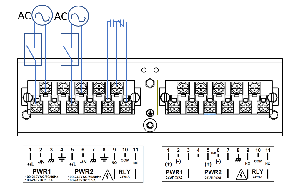

To establish AC power connection with the power source turned off, follow the steps below. When following the instructions, refer to Figure 1.
If an AC power supply has been installed in PS1, perform steps 2 through 4 on the left hand terminal block. Please note that if there are no DC power supplies installed on the iMR350 then the right hand terminal block will not be populated.
If an AC power supply has been installed in PS2, perform steps 5 through 7.
To keep the wires from pulling loose, use a small flat-blade screwdriver to tighten the wire-clamp screws on the front of the terminal block connector.
All equipment must be installed according to applicable local wiring codes and standards.
Always use cables that are rated for the operating ambient temperature of 85°C.
For 100-240 VAC rated equipment, protection for earth fault is provided by max. 20 A branch circuit from AC input in building installation. The protection in the building installation is relied upon for short-circuit backup protection.
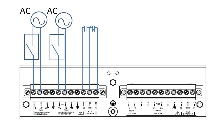
To establish AC power connection with the power source turned off, follow the steps below. When following the instructions, refer to Figure 1.
If an AC power supply has been installed in PS1, perform steps 2 through 4 on the left hand terminal block. Please note that if there are no DC power supplies installed on the iMR350 then the right hand terminal block will not be populated.
If an AC power supply has been installed in PS2, perform steps 5 through 7.
To keep the wires from pulling loose, use a small flat-blade screwdriver to tighten the wire-clamp screws on the front of the terminal block connector.
Equipment must be installed according to applicable local wiring codes and standards.
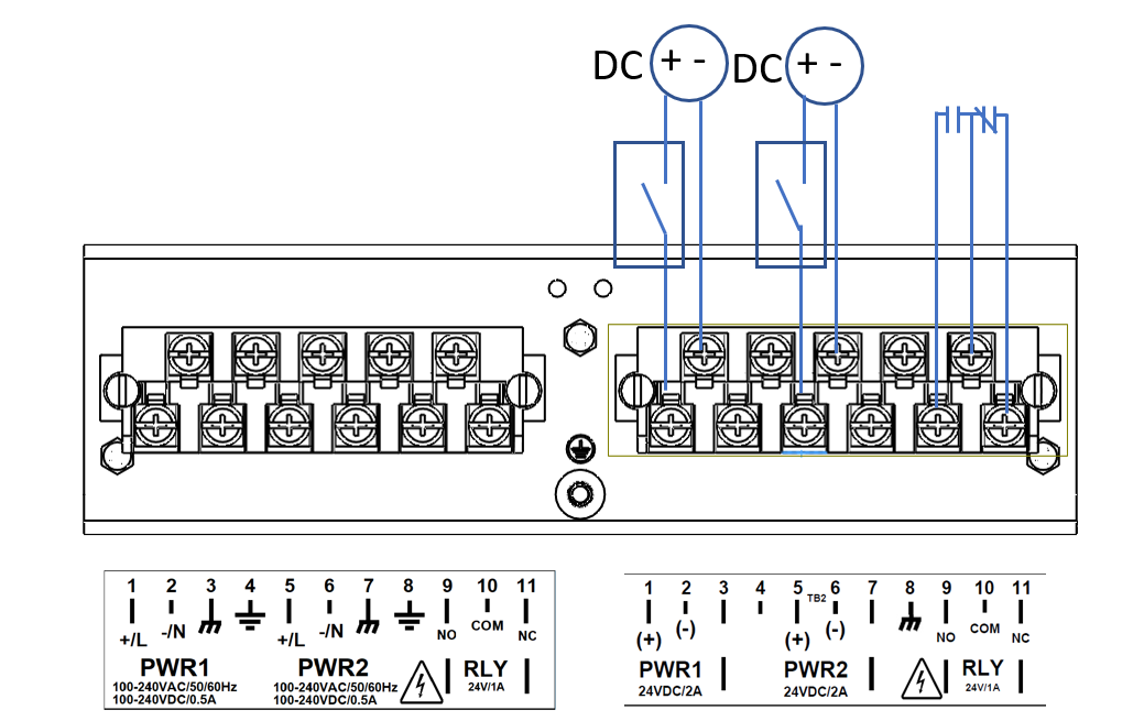
With the power source turned off, refer to figure Figure 3 and perform the following steps:
For a DC Power Supply in PS1, carry out steps 1 through 2, by wiring the right hand terminal block. Please note that if there are no AC power supplies installed on the iMR350 then the left hand terminal block will not be populated.
If a DC Power Supply has been installed in PS2, perform the following steps.
After wiring is completed, perform the following:
Equipment must be installed according to applicable local wiring codes and standards.
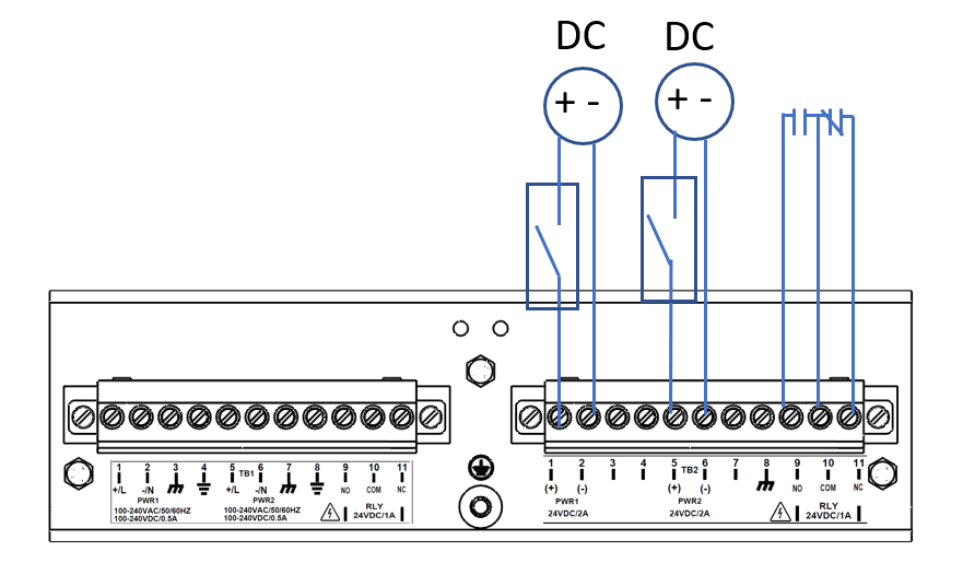
With the power source turned off, refer to figure Figure 3 and perform the following steps:
For a DC Power Supply in PS1, carry out steps 1 through 2, by wiring the right hand terminal block. Please note that if there are no AC power supplies installed on the iMR350 then the left hand terminal block will not be populated.
If a DC Power Supply has been installed in PS2, perform the following steps.
After wiring is completed, perform the following:


The user shall be responsible for ensuring the integrity of any protective conductor connections before carrying out any other actions.