IP (Internet Protocol)
is an identifier for a computer or device on a TCP/IP network. Networks
using the TCP/IP protocol route
messages based on the IPaddress
of the destination. The format of an IP address is
a 32-bit numeric address written as four numbers separated by periods.
Each number can be zero to 255 (e.g. 10.5.25.180).
Every computer that communicates over the Internet is assigned
an IP address that uniquely identifies the
device and distinguishes it from other computers on the Internet.
Within an isolated network, IP addresses can be assigned at random
as long as each one is unique. However, to connect a private network
to the Internet, the registered IP addresses
must be used (called Internet addresses) to avoid duplicates. The
four numbers in an IP address are
used in different ways to identify a particular network and a host
on that network.
Four regional Internet registries—ARIN, RIPE NCC, LACNIC and
APNIC—are used to assign Internet addresses from the following three
classes.
- Class A—supports 16 million hosts on each of 126
networks
- Class B—supports 65,000 hosts on each of 16,000 networks
- Class C—supports 254 hosts on each of 2 million networks
The number of unassigned Internet addresses is running out, so
a new classless scheme called CIDR (Classless Inter-Domain Routing)
is gradually replacing the system based on classes A, B, and C and
is tied to adoption of IPv6.
ICMP (Internet Control Message
Protocol) is an extension to the IP defined by RFC 792. ICMP supports packets containing
error, control, and informational messages. For example, the ping
command uses ICMP to test an
Internet connection.
Either the IPv4 Module or
the Linux IP can be used.
IP (Internet Protocol) functions at network layer. IP delivers/forwards packets to the
higher layer and to other hosts/routers. The forwarding table maintained
by IP consists of static routers
and the routes learnt from other routing protocols.
To access IP screens, go to .
The IP are configured through the screens
displayed by the following tabs:
VLAN Interface Basic Settings
IPv4 Interface Settings
IP Route Configuration
Loopback Basic Settings
IVR–VLAN Mapping
IP/ICMP Settings
IP PMTU
Static ARP
IP Ping
IPv4 Trace Route
By default, the tab IP displays the VLAN
Interface Basic Settings screen.
Note: IP is the first feature shown in
the Layer 3 Management.
VLAN Interface Basic Settings
Figure 1. VLAN Interface Basic Settings
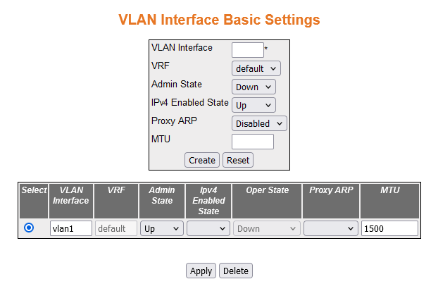
| Screen Objective |
This screen allows the user to configure the
basic settings of the VLAN interface. |
Note: The IPv4 enabled state
is dependent on the Admin status. If Admin state is down, IPv4 Enabled state
is down.
|
| Navigation |
|
| Fields |
- Select—select
the VLAN Interface for which
configuration needs to be modified or deleted.
- VLAN Interface—enter the VLAN/VFI ID for the Interface to
be created. The value ranges from 1 to 65535.
- <vlan –id>—this
is a unique value that represents the specific VLAN. This value ranges from 1
to 4094
- <vfi-id>—VFI ID is a VLAN created
in the system which contains Pseudo wires and attachment Circuits
as member ports. This creates a logical LAN for
the VPLS service. This value ranges from 4096 to 65535.
Note: The VLAN ID 4095 is reserved and may
be used to indicate a wildcard match for the VID in management operations
or Filtering Database entries.
VFI IDs 4096 and 4097 are reserved
identifiers used in MPLS PW.
The theoretical maximum for the
maximum number of VFI is 65535 but the actual number of VFI supported
is a sizing constant. Based on this, the maximum number of VFI ID accepted
in the management interface is restricted. For example, if 100 VFIs
are supported, the maximum number of VFI supported will be restricted
to maximum number of VLANs +
100. An error message is displayed for any value beyond this range.
- Switch—default.
- VRF—select VRF. The default option is
default.
- Admin State—select the Admin Status of
the VLAN interface. The default option
is Down. The list contains:
- Up—sets
the IP interface administratively
up. After Configuring the IP address, the interface can be made
admin UP.
- Down—sets the IP interface
administratively down.
- IPv4 Enabled State—select the status
of IPv4 on the VLAN interface. The default option
is UP. The list contains:
- UP—enables IPv4 on
the specified interface.
- Down—disables IPv4 on the
specified interface.
- Oper State—displays the current operational
status of the VLAN interface. The
list contains:
- Up—specifies that the interface is operationally
up and ready to transmit and receive network traffic.
- Down—specifies that the interface is operationally down.
- Proxy ARP—select the Proxy ARP admin status for the interface.
The default option is Disabled. The list contains:
- Enabled—enables
Proxy ARP feature for the interface.
- Disabled—disables Proxy ARP feature
for the interface.
|
| Fields (cont) |
- MTU—enter the
Maximum Transmission Unit (MTU).
The MTU for the interface as shown
to the higher interface sub-layer (this value should not include the
encapsulation or header added by the interface). If IP is operating
over the interface, then this value indicates the IP MTU over this interface. The default
value is 1500. This value ranges from 46 to 9216.
Note: To configure
the MTU value, the Admin State
of the interface should be Down.
|
| Buttons |
- Create—adds
and saves new configuration.
- Reset—resets to default value for respective
fields and discards all user input.
- Apply—modifies attributes and saves the
changes.
- Delete—deletes the selected entry.
|
IPv4 Interface Settings
Figure 2. IPv4 Interface Settings

| Screen Objective |
This screen allows the user to configure the
settings of the IPv4 interface. |
| Navigation |
|
| Fields |
- Select—select
the VLAN Interface for which
configuration needs to be modified or deleted.
- Interface ID—select the index value which
uniquely identifies the VLAN interface
to which this entry is applicable.
Note: The interface id can
be created from the VLAN Interface
Basic Settings screen.
- Get IP Address Mode / IP Allocation—select
the protocol to be used to obtain the IP address from the interface.
The default option is RARP. The
list contains:
- Manual—configures the IP address
manually to a specified address by the user or administrator.
- RARP—assigns the IP address
to the system by a RARP (Reverse Address
Resolution Protocol) server.
- DHCP—assigns the IP address to the system by a DHCP (Dynamic Host Configuration
Protocol) server. DHCP-client
tries for dynamic IP address from
server for maximum number of retries. If not successful in receiving
any IP address, then rolls back
to default IP address
- VRF—the assigned VRF. By default is default.
- IP Address—enter the IP address of the interface. If the
interface is not a network interface, then the default value of
0.0.0.0 is assigned and the interface is treated as a non-numbered
interface by IP.
- Subnet Mask—enter the subnet mask for
the provided IP address.
- Broadcast Address—displays the broadcast
address for the specified IP address.
- Address Type—select the type of IP address for the specified VLAN
interface. The default option is Primary. The list contains:
- Primary—sets
the address type as Primary IP address
for the specified interface
- Secondary—sets the address type as secondary IP address this is an additional IP address that can be configured
for the specified interface.
Note: The secondary IPaddress can be created only if
the primary IP address is already
created for the interface.
|
| Buttons |
- Modify—adds
and saves new configuration.
- Reset—resets to default value for respective
fields and discards all user input.
- Delete—deletes the selected entry.
|
IP Route Configuration
Figure 3. IP Route Configuration

| Screen Objective |
This screen allows the user to configure IP route information. |
| Navigation |
|
| Fields |
- Select—select
the destination network for which configuration needs to be modified
or deleted.
- Destination Network—enter the destination IP address of the route. It denotes
the Network Address for which the route is being added.
- Subnet Mask—enter the subnet mask for
the provided IP address.
- Next Hop—select a Next Hop option. The
options are:
- Gateway—enter the Next Hop gateway to
reach the Destination Network.
- Interface—select the outgoing interface
through which the Destination Network is reachable.
Note: The
interface id can be created from the VLAN Interface
Basic Settings screen.
- VRF—select VRF. The default option is
default.
- Switch—default.
- Distance (Metric)—enter the metric value
of the destination. The semantics of this metric are determined
by the routing-protocol. The value ranges from 1 to 255. The default
value is 1.
- Routing Protocol—displays the status
of the routing protocol through which the route was learnt, if the
route is not a directly connected network or a static route.
|
| Buttons |
- Add—adds and
saves new configuration.
- Reset—resets to default value for respective
fields and discards all user input.
- Apply—modifies attributes and saves the
changes.
Note: Only static routes can be deleted or modified.
- Delete—deletes the selected entry.
|
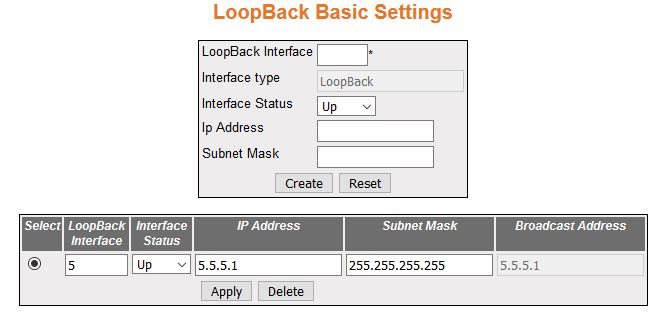
Loopback Basic Settings
Figure 4. Loopback Basic Settings
| Screen Objective |
This screen allows the user to configure the
basic loopback settings. |
| Navigation |
|
| Fields |
- LoopBack Interface—enter
a number for the Loopback Interface that is to be created.
- Interface type—displays the interface
type as Loopback.
- Interface Status—select the interface
status of the loopback. The list contains:
- Up—allows traffic
through the specified loopback interface.
- Down—does not allow traffic through the specified loopback interface.
- IP Address—enter the IP address for the Loopback interface.
- Subnet Mask—enter the subnet mask for
the provided IP address.
- Broadcast Address—enter the broadcast
address for the Loopback interface.
|
| Buttons |
- Create—adds
and saves new configuration.
- Reset—resets to default value for respective
fields and discards all user input.
- Apply—modifies attributes and saves the
changes.
Note: Only static routes can be deleted or modified.
- Delete—deletes the selected entry.
|
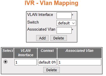
IVR–VLAN Mapping
Figure 5. IVR–VLAN
Mapping
| Screen Objective |
This screen allows the user to configure the
list of VLANs to be associated
for an Inter VLAN Routing (IVR)
interface. |
| Navigation |
|
| Fields |
- VLAN Interface—enter
the primary IVR interface ID to
which the VLAN or list of VLANs should be mapped. This value
ranges from 1 to 4094.
Note: The interface ID uniquely identifies
a specific VLAN that can be created in
the system through the VLAN Interface
Basic Settings screen.
Note: The VLAN or
list of VLANs can be mapped only
to the IVR interfaces already
created in the system.
- Switch—default.
- Associated VLANS—enter the VLAN ID or list of VLAN IDs to be mapped with the
specified IVR interface. The format of this entry for VLAN list is VLAN ID, VLAN ID.
Example: 2,7,9.
Note: The VLANs
can be mapped to only one IVR interface.
That is, the VLAN associated
to one IVR interface cannot be
associated to another IVR interface.
|
| Buttons |
- Add—adds and
saves new configuration.
- Delete—deletes the selected entry.
|
IP/ICMP Settings
Figure 6. IP/ICMP
Settings
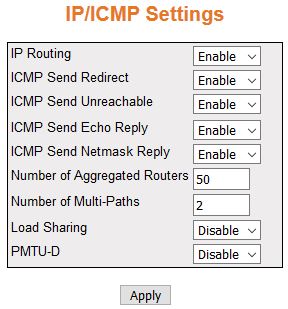
| Screen Objective |
This screen allows the user to configure the IP Information. |
| Navigation |
|
| Fields |
- IP Routing—select
the IP routing status. The default
option is Enable. The list contains:
- Enable—enables the IP routing status for configuring IP information.
- Disable—disables the IP routing
status for configuring IP information.
- ICMP Send Redirect—select the ICMP Send redirect status on an
interface basis. The default option is Enable. The list contains:
- Enable—allows sending ICMP Redirect
Message
- Disable—does not allow sending ICMP Redirect
Message
|
| Fields (cont) |
- ICMP Send Unreachable—select
the ICMP Send unreachable status
on an interface basis. The default option is Enable. The list contains:
- Enable—allows sending ICMP unreachable
Message
- Disable—does not allow sending ICMP unreachable
Message
- ICMP Send Echo Reply—select the ICMP Send Echo reply status on
an interface basis. The default option is Enable. The list contains:
- Enable—allows sending ICMP Echo
reply Message
- Disable—does not allow sending ICMP Echo reply Message
- ICMP Send Netmask Reply—select the ICMP Send Netmask Reply status
on an interface basis. The default option is Enable. The list contains:
- Enable—allows sending ICMP Netmask
Reply Message
- Disable—does not allow sending ICMP Netmask
Reply Message
- Number of Aggregated Routers—enter the
number of aggregated routes that can be configured in the system.
This value will come in to effect only after rebooting the router.
The value ranges from 5 to 4095.
- Number of Multi-Paths—enter the number
of multi-paths in the routing table. The value ranges from 1 to
16. The default value is 2.
- Load Sharing—enter the load sharing status.
The default option is Disable. The list contains:
- Enable—allows
the distribution of the load available in the equal cost multi-paths
- Disable—does not allow the distribution of the load available
in the equal cost multi-paths
- PMTU-D—select this object to enable or
disable the PMTU-D on all paths globally.
The default option is Disable. The list contains:
- Enable—overrides
the route-based and application-level requests for PMTU-D.
- Disable—PMTU-D is not done
even if the application requests to do so.
Note: To
configure RARP PMTU, PMTU-D
(Path Maximum Transmission Unit- Discovery) field should be enabled.
|
| Buttons |
- Apply—modifies
attributes and saves the changes.
|
IP PMTU
Figure 7. IP PMTU Configuration
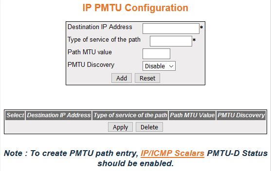
| Screen Objective |
This screen allows the user to configure the
IP PMTU. |
| Navigation |
|
| Fields |
- Select—click
to select configured destination IP address for which the configuration
needs to be re-applied.
- Destination IP Address—enter the destination
IP address of the path for which the discovery is made.
- Type of service of the path—enter the
type of service of the path. The value ranges from 0 to 255.
Note: To
create PMTU path entry, IP/ICMP
Settings should be enabled.
- Path MTU value—enter the value of the PMTU discovered. If the admin changes
this value, PMTU discovery on
that path is stopped. The value ranges from 68 to 65535.The default
option is 255.
- PMTU Discovery—select the status of PMTU discovery. The options are:
- Enable—enables the PMTU discovery
for the given path to override the application request with respect
to PMTU-D.
- Disable—disables the PMTU discovery.
|
| Buttons |
- Add—adds and
saves new configuration.
- Reset—resets to default value and discards
all user input.
- Apply—modifies attributes and saves the
changes.
- Delete—deletes the selected entry.
|
Static ARP
Figure 8. Static
ARP

| Screen Objective |
This screen allows the user to configure the
static (Address Resolution Protocol) ARP entry
settings. The ARP finds the
hardware address of the client and stores it in an ARP cache. The ARP entry can be configured manually
by using this dialog box. The entry is stored permanently in the
ARP cache as a static entry.
|
| Navigation |
|
| Fields |
- Select—click
to select configured VLAN interface for which the configuration
needs to be re-applied.
- Interface—adds a static entry in the ARP cache for the specified interface.
Note: Interface
can be created in Layer 3 Management > IP > IPv4 AddrConf
- IP Address—enter the IP address or alias
to map to the specified MAC address.
- Physical Address—enter the MAC address
to map to the specified IP address or IP alias.
|
| Fields (cont) |
- Type—displays
the static entry in the ARP cache
for the specified interface. This field is greyed out.
- Fast
Ethernet—officially referred to as 100BASE-T standard. This is a version
of LAN standard architecture that
supports data transfer up to 100 Megabits per second.
- Gigabit Ethernet—a version of LAN standard
architecture that supports data transfer unto 1 Gigabit per second.
- Extreme Ethernet—a version of Ethernet that supports data transfer up
to 10 Gigabits per second. This Ethernet supports only full duplex links.
- i-lan—internal LAN created
on a bridge per IEEE 802.1ap.
- Status—displays the status of the static
entry in the ARP cache for the specified
interface.
|
| Buttons |
- Create—adds
and saves new configuration.
- Reset—resets to default value and discards
all user input.
- Apply—modifies attributes and saves the
changes.
- Delete—deletes the selected entry.
|
IP Ping
Figure 9. IP Ping Entry
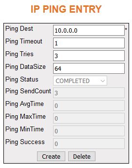
| Screen Objective |
This screen allows the user to configure the
IP PING entry settings. The
Packet Internet Groper (PING)
module is built based on the ICMP echo request
and ICMP echo response messages.
The network administrator uses the Ping to
verify the presence of a remote device. Ping involves sending ICMP echo
messages repeatedly and measuring the time between transmission
and reception of message. The output displays the time taken for
each packet to be transmitted, number of packets transmitted, number
of packets received, and packet loss percentage.
|
| Navigation |
|
| Fields |
- Ping Dest—enter
the destination IP address of the
node to be pinged.
- Ping Timeout—enter the time in seconds
after which the entity waiting for the ping response times out.
This value ranges from 1 to 100.
- Ping Tries—enter the number of tries
in which the data need to be pinged. The value ranges form 1 to1000.
|
| Fields |
- Ping Datasize—enter
the size of the data need to be pinged. The value ranges from 0
to 2080.
- Ping Status—displays the status of the
data that is pinged. This field is greyed out.
- PROGRESS—indicates
the ping status as in progress.
- COMPLETED—indicates the ping status as completed.
- NOT INITIATED—indicates the ping status as not initiated
- Ping Datasize—enter the size of the data
need to be pinged. The value ranges from 0 to 2080.
- Ping SendCount—displays the send count
of the pinged data.
- Ping AvgTime—displays the average time
taken for pinging data.
- Ping MaxTime—displays the maximum time
taken for pinging data.
- Ping MinTime—displays the minimum time
taken for pinging data.
- Ping Success—displays the success count
of the pinged data.
|
| Buttons |
- Create—adds
and saves new configuration.
- Delete—deletes the selected entry.
|
IPv4 Trace Route
Figure 10. IPv4
Trace Route
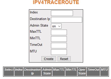
| Screen Objective |
This screen allows the user to configure the IPv4 trace route settings. |
| Navigation |
|
| Fields |
- Select—click
to select configured index for which the configuration needs to
be re-applied.
- Index—enter the index value to configure
information about a particular IP trace route operation. This value
ranges from 0 to 10.
- Destination IP—enter the destination IP address of the path for which
the trace route is made.
- Admin State—select the status for the
traceroute operation. The default option is on. The list contains:
- On—Sets the trace operation status as in progress.
- Off—Does not sets the trace operation status as in progress.
- Max TTL—enter the maximum value of the TTL field to be filled up in the IP
packets used for the traceroute. The value ranges from 1 to 99.
The default value is 15.
- Min TTL—enter the maximum value of the TTL field to be filled up in the IP packets used for the traceroute.
The value ranges from 1 to 99. The default value is 15.
|
| Fields (cont) |
- Operational State—displays
the current status for the traceroute operation.
- In progress—displays
the current status for the traceroute operation as in progress.
- Not In progress—displays the current status for the traceroute
operation as not in progress.
- Time Out—enter the interval in seconds
between consecutive trace requests. The value ranges from 1 to 2147483647.
- MTU—enter number of octets of data to
be sent in trace packets. The value ranges from 1 to 2147483647.
|
| Buttons |
- Create—adds
and saves new configuration.
- Reset—resets to default value and discards
all user input.
- Delete—deletes the selected entry.
|