This section describes how to configure the Dynamic Host
Configuration Protocol Relay on the switch.
DHCP Relay (Dynamic
Host Configuration Protocol Relay) agent is a host or an IP router
that allows the DHCP client and DHCP server in different subnets
to communicate with each other, so that the DHCP client
can obtain its configuration information while booting.
DHCP Relay agent is used to
forward DHCP packets between
client and server when they are not in the same subnets. The relay
receives packets from the client and inserts certain information
such as network from which the packet is removed and then forwards
it to the server. The server identifies the client’s network from
this information and allocates IP accordingly, then sends the reply
to the relay. The relay strips the information inserted and broadcasts
the packets into the client’s network.
To access DHCP Relay screens, go to .
DHCP Relay Configuration
By
default, the tab Basic Settings displays
the DHCP Relay Configuration screen.
Figure 1. DHCP Relay Configuration
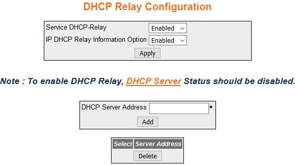
| Screen Objective |
This screen allows the user to configure the
basic DHCP Relay information. |
Note: To enable DHCP Relay, DHCP Server
Status should be disabled.
|
| Navigation |
|
| Fields |
- Select—select
the interface for which configuration need to be applied or deleted.
- Service DHCP-Relay—select the Service DHCP relay status in the switch.
The default option is Disabled. The list contains:
- Enabled—enables
the DHCP relay service i.e. Relay
Agent becomes active in the switch. DHCP relay
agent relays DHCP messages between DHCP client and DHCP server located in different
subnets.
- Disabled—disables the DHCP relay
service in the switch
Note: The service DHCP relay can be set as Enabled,
only if the DHCP Server is set as
Disabled.
- IP DHCP Relay Information Option—select
the Service DHCP relay status
in the switch. The default option is Disabled. The list contains:
- Enabled—enables the controlling status of the processing related
to the Relay Agent Information options for inserting the necessary
information while relaying a packet from a client to a server and
examining/stripping of the inserted information when relaying a
packet from a server to a client.
- Disabled—disables the controlling status of the processing related
to the Relay Agent Information options
- Server Address—displays the IP address
of the DHCP Server to which the
Relay Agent needs to forward the packets from the client. A maximum
of 5 servers can be configured. If no servers are configured, the DHCP packets will be broadcast
to entire network, except the network from which packet was received.
|
| Buttons |
- Apply—modifies
attributes and saves the changes.
- Add—adds and saves new configuration.
- Delete—deletes the selected entry.
|
DHCP Relay Interface Configuration
Figure 2. DHCP Relay Interface Configuration
| Screen Objective |
This screen allows the user to configure a DHCP address pool. A DHCP address pool is used by the
servers to allocate IP addresses to clients. |
| Navigation |
|
| Fields |
|
| Buttons |
- Create—adds
and saves new configuration.
- Reset—resets to default value for respective
fields and discards all user input.
- Apply—modifies attributes and saves the
changes.
- Delete—deletes the selected entry.
|
