Serial Console

Connect a PC or terminal directly to the serial console to access the boot-time control and RAPTOR’s interfaces. The serial console port provides access to the console interface.
The serial console port is RS232 with RJ45 connector with a console cable and port setup of 115200 bps, 8, N.


RS232 RJ-45 pin assignments are as follows:
| PIN # | TYPE | ASSIGNMENT |
|---|---|---|
| 1 | RS232 | RTS |
| 2 | RS232 | |
| 3 | RS232 | TX |
| 4 | RS232 | GND |
| 5 | RS232 | GND |
| 6 | RS232 | RX |
| 7 | RS232 | |
| 8 | RS232 | CTS |
Ethernet Ports & Communication Cabling
The RAPTOR comes with standard Ethernet ports. According to the link type, the switch uses CAT 3, 4, 5, and 5e UTP cables to connect to any other network devices (computers, servers, switches, routers, or hubs).
For RJ-45 cable specifications, refer to the following table.
| CABLE | TYPE | MAXIMUM LENGHT |
|---|---|---|
| 10BASE-T | Cat. 3, 4, 5 100 Ω UTP | 100 m (328 ft) |
| 100BASE-TX | Cat. 5 100 Ω UTP | 100 m (328 ft) |
| 1000BASE-T | Cat. 5/Cat. 5e 100 Ω UTP | 100 m (328 ft) |
RJ45 Ethernet Pin Assignments
With 10/100/1000BASE-T(X) cables, pins 1 and 2 are used for transmitting data, and pins 3 and 6 for receiving data.
10/100 Base-T(X) RJ-45 pin assignments are as follows:| PIN # | TYPE | ASSIGNMENT |
|---|---|---|
| 1 | 10/100 Base-T(X) | TD+ |
| 2 | 10/100 Base-T(X) | TD- |
| 3 | 10/100 Base-T(X) | RD+ |
| 4 | 10/100 Base-T(X) | Not used |
| 5 | 10/100 Base-T(X) | Not used |
| 6 | 10/100 Base-T(X) | RD- |
| 7 | 10/100 Base-T(X) | Not used |
| 8 | 10/100 Base-T(X) | Not used |
1000 Base-T RJ-45 pin assignments are as follows:
| PIN # | TYPE | ASSIGNMENT |
|---|---|---|
| 1 | 1000 Base-T | BI_DA+ |
| 2 | 1000 Base-T | BI_DA- |
| 3 | 1000 Base-T | BI_DB+ |
| 4 | 1000 Base-T | BI_DC+ |
| 5 | 1000 Base-T | BI_DC- |
| 6 | 1000 Base-T | BI_DB- |
| 7 | 1000 Base-T | BI_DD+ |
| 8 | 1000 Base-T | BI_DD- |
| PIN # | MDI PORT | MDI-X PORT |
|---|---|---|
| 1 | TD+ (transmit) | RD+ (receive) |
| 2 | TD- (transmit) | RD- (receive) |
| 3 | RD+ (receive) | TD+ (transmit) |
| 4 | Not used | Not used |
| 5 | Not used | Not used |
| 6 | RD-(receive) | TD-(transmit) |
| 7 | Not used | Not used |
| 8 | Not used | Not used |
1000 Base-T RJ-45 pin assignments are as follows:
| PIN # | MDI PORT | MDI-X PORT |
|---|---|---|
| 1 | BI_DA+ | BI_DB+ |
| 2 | BI_DA- | BI_DB- |
| 3 | BI_DB+ | BI_DA+ |
| 4 | BI_DC+ | BI_DD+ |
| 5 | BI_DC- | BI_DD- |
| 6 | BI_DB- | BI_DA- |
| 7 | BI_DD+ | BI_DC+ |
| 8 | BI_DD- | BI_DC- |
“+” and “-” signs represent the polarity of the wires that make each wire pair.
Recommendations for Cables in High Electrical Noise
Constant electrical noise can be due to the predictable 50 or 60 Hz AC 'hum' from power circuits or harmonic multiples of power frequency close to the data communications cable.
Follow these recommendations for copper data cabling in high electrical noise environments:
- Data cable lengths should be as short as possible, preferably 3 m (10 ft) in length. Copper data cables should not be used for inter-building communications.
- Power and data cables should not be run in parallel for long distances, and they should be installed in separate conduits. Power and data cables should intersect at 90° angles when necessary to reduce inductive coupling.
- Ground loops which are major cause of noise propagation must be avoided.
SFP
The RAPTOR supports fiber optic ports that can connect to other devices using SFP (Small Form-factor Pluggable) modules. The fiber optical ports are MultiMode (MM) or SingleMode (SM) with LC connectors.
Always connect the TX port of Switch A to the RX port of Switch B.
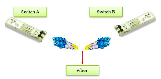
The SFP modules are available separately from the Accessories list.

The dimensions are in millimeters (inches)
The main difference between MM and SM fibers is that the former has much larger core diameter. Typically, MM has a core diameter of 50 or 62.5 µm and a cladding diameter of 125 µm, while a typical SM fiber has a core diameter between 8 and 10 µm and a cladding diameter of 125 µm.

SM fibers are better suited for moving information across longer distances and are routinely used by telecommunications. In comparison, MM fibers are ideal for local networks due to their low cost and greater bandwidth.

- Wear finger cots or gloves. Your hands may look clean, but dirt and oils on them can damage the fiber and contaminate connectors.
- Never use the fiber pigtail to pick up or support the weight of the device. Keep both the device and the optical connector together in your hand(s).
- The fiber is made of a very pure expensive glass. Treat it with the same care that would be used when handling expensive crystal glass.
- Do not allow kinks or knots to develop in the fiber. Do not pull on the fiber when kinks or knots are present. Pulling will only cause knots, kinks, and curls to tighten and exceed the minimum bend radius.
- Always use the correct tools for stripping and cleaving the fiber. It will save time and reduce breakage caused by scratches.
- Follow all ESD precautions.