The Port Manager link helps to configure parameters of the ports such as MTU, IP specific configuration, and WAN interface specific configuration such as maximum burst size.
To access Port Manager screens, go to .
Welcome to Layer 2 Management Page
By default, the tab Basic Settings displays the Port Basic Settings screen.
Port Manager is the first option from the Layer 2 Management features. The Welcome to the Layer 2 Management Page is as shown below.

Port Basic Settings
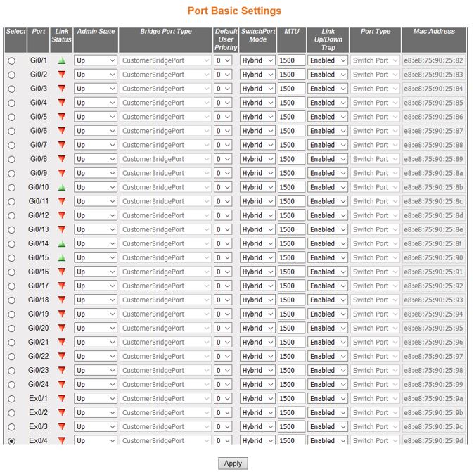
| Screen Objective | This screen allows the user to configure general information applicable for all physical ports in a switch on port basis. All physical ports of the switch can be customized at any time. |
| Navigation |
|
| Fields |
|
| Fields (cont) |
|
| Fields (cont) | Note: Bridge port type can be set only for
switch ports and not for router ports, IVR interfaces, and I-LAN
interfaces.
The port type can be set only as CustomerBridgePort in customer bridges. The port type can be set only as ProviderNwPort in provider core and edge bridges. The port type can be set only as CustomerNwPort or ProviderNwPort, in provider backbone bridge. The port types CustomerEdgePort and PropCustomerEdgePort, are allowed only in PEBs. The port type cannot be set for a port-channel port if physical ports are aggregated in the port-channel. The port type cannot be set for a port that is a part of a port-channel.
Note: This
priority is useful only on media, such as Ethernet, that does not
support native user priority.The default user priority is greyed
out and cannot be configured if the Port Type is set as Router Port.
|
| Fields (cont) | Note: The switch port mode can be set to Access
for a port, only if the Dynamic VLAN status
is set as Disabled, and Acceptable Frame Type is set as UnTagged
and Priority Tagged for that port.
The switch port mode can be set to Trunk for a port, only if the port is not a member of Untagged Ports for a VLAN. The switch port mode is greyed out and cannot be configured if the Port Type is set as a Router Port. A host port can be associated only with one secondary VLAN and with the associated primary VLAN. Promiscuous ports should be configured as member port of primary VLAN and member port of all secondary VLANs associated with that primary VLAN. Host and promiscuous ports should be configured as untagged members of primary / secondary VLANs. An access / hybrid port automatically changes as a host port, when configured as a member port of a primary/secondary VLAN. Ingress Filtering cannot be disabled on host and promiscuous ports. The port is removed from the associated PVLAN domain, when the mode is changed from promiscuous / host to access/hybrid.
Note:
The MTU value can be changed for the interface, only if the Admin State of the interface is set as Down.The MTU value should be set as lowest of the MTU values of the member ports, while configuring for logical VLAN interfaces. |
Note:
The port type can be configured, only if the Admin State of the interface is set as Down.
Note:
The MAC address can be configured only if the Admin State of the interface is set as Down.This field is valid only if the type/protocol of interface is ethernetCsmacd (Ethernet/802.3) or ieee8023ad (Link Aggregation MIB). |
|
| Buttons |
|

VLAN Traffic Class Mapping
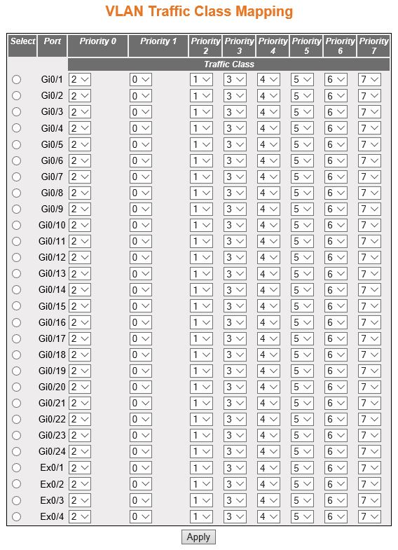
| Screen Objective | This screen allows the user to map evaluated user priority onto traffic class for forwarding by the bridge. For handling priority traffic, eight traffic classes are supported. Traffic types are assigned based on the time sensitiveness of the traffic. Traffic class is used to meet the latency and throughput requirement of time-critical traffic in a LAN environment, where both time-critical and non-time-critical traffic compete for the network bandwidth |
Note:
The number of supported traffic classes depends on the hardware used, which may limit the number of traffic classes to a lower number. |
|
| Navigation |
|
| Fields |
|
| Buttons |
|
Port Control
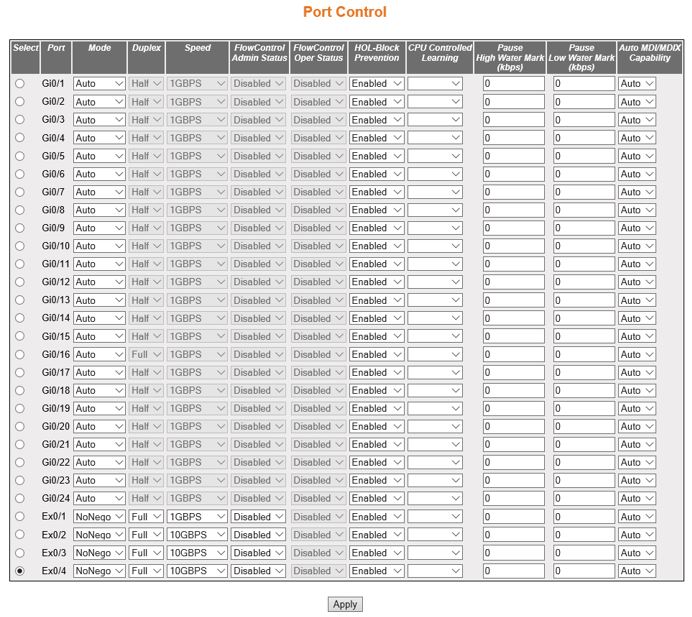
| Screen Objective | This screen allows the user to configure port specific parameters, such as negotiation mode of the switch. |
| Navigation |
|
| Fields |
|
| Fields (cont) |
|
| Fields (cont) | Note:
The speed can be configured, only if the negotiation Mode is set as NoNego. The speed is automatically configured based on the hardware after negotiating with the peer if the negotiation Mode is set as Auto.
|
| Fields (cont) |
|
| Buttons |
|
Storm Control
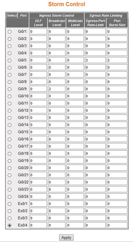
| Screen Objective | This screen allows the user to control the rate limiting parameters for all interfaces in the switch. The rate control feature protects the switch from packet flooding from malicious users. This feature allows the user to set threshold traffic rate so that the traffic exceeding the threshold rate is dropped. Rate control can be applied on unknown unicast, multicast, and broadcast traffic. |
| Navigation |
|
| Fields |
|
| Fields (cont) |
|
| Buttons |
|
Port Role

| Screen Objective | This screen allows the user to configure the port role related parameters. |
| Navigation |
|
| Fields |
|
| Buttons |
|