This section describes how to configure Media Redundancy
Protocol (MRP) on the switch using
the WebUI.
MRP (Media
Redundancy Protocol) is a networking protocol designed to implement
redundancy and recovery in a ring topology. MRP is
designed to react deterministically on a single failure on a switch
in the MRP ring. An MRP instance is configured between
two ports known as ring ports and can act as manager or client in
the ring. The MRP node which is
configured as Manager has the responsibility of avoiding the loop
in the ring by making one ring port as blocking and other as forwarding.
The convergence time of MRP is
very fast as compared to spanning tree protocols. On a port, either MRP can be enabled or spanning tree
may be selected.
The ring size may consist of up to 50 devices while still meeting
the 200 ms reconfiguration requirement.
To access MRP screens, go to .
Global Settings
The Global
Settings screen is used to enable or disable MRP on the switch.
Figure 1. Global
Settings

| Screen Objective |
This screen allows the user to enable or disable MRP. |
| Navigation |
|
| Fields |
- Global Status—
select Disable or Enable to change the status of the protocol.
|
| Buttons |
- Apply—modifies
attributes and saves the changes.
|
MRP Configuration
Figure 2. MRP Configuration
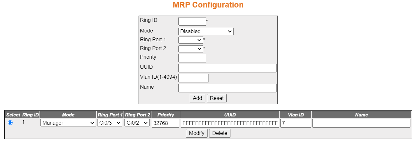
| Screen Objective |
This screen allows the user to create, modify,
and delete a ring instance. These parameters are necessary for the
configuring the ring mode and ring ports. This configuration page
can be used to create a ring instance with VLAN ID
or modify the VLAN ID on the
existing ring instance. VLAN ID
is an optional parameter such as name and domain ID. Configuring VLAN ID on this page, enables MRPRING
protocol to sent the signaling frames (test and control) with IEEE
802.1Q VLAN tags with the given VLAN and priority of 7. |
| Navigation |
|
| Fields |
- Ring ID—the
ring identifier of the MRP instance.
This is a numeric value with a range of 1 through 2.
- Mode—a drop-down list with the following options:
- Disabled
- Client—enter this to configure MRP instance
as client (MRC) in the MRP ring, which forwards the test
frames between the ring ports.
- Manager—enter this to configure MRP instance
as manager (MRM) in the MRP ring, which generates the test
frames on both ring ports and handles/avoid the loop.
- Manager-Autocomp—enter this to configure MRP instance
as manager auto (MRA) in the MRP ring. It competes with the other MRA nodes in the ring to become MRM based on priority. If priority
is the highest, it turns to act as MRM else
turn MRC.
- Ring Port 1—this is a drop-down selector for the port
to be selected as Port 1 of the ring.
- Ring Port 2—this is a drop-down selector for the port
to be selected as Port 2 of the ring.
- Priority—this is a value between 0 and 65535, Enter to
configure MRP priority to be manager
(MRM) in the ring, in case auto
manager is enabled.
- UUID—enter this to configure MRP UUID as 32 octet string (hex).
The UUID is a 128-bit identifier
unique to a domain/ring. All MRP instances
belonging to the same ring must have the same domain ID.
- Vlan ID (1-4094)—enter a number from 1 to 4094 to assign
a Vlan ID to a ring instance.
- Name—an optional field that assigns a name to the ring
configuration.
|
| Buttons |
- Add—adds the
configuration to the switch.
- Reset—clears the fields in the form
- Modify—by selecting a configuration with the radial button
and then clicking modify, the user will be able to edit a configuration.
- Delete—the user first selects a configuration with the
radial button and then clicks delete to remove it.
|
MRP Status
Figure 3. MRP Status Screen
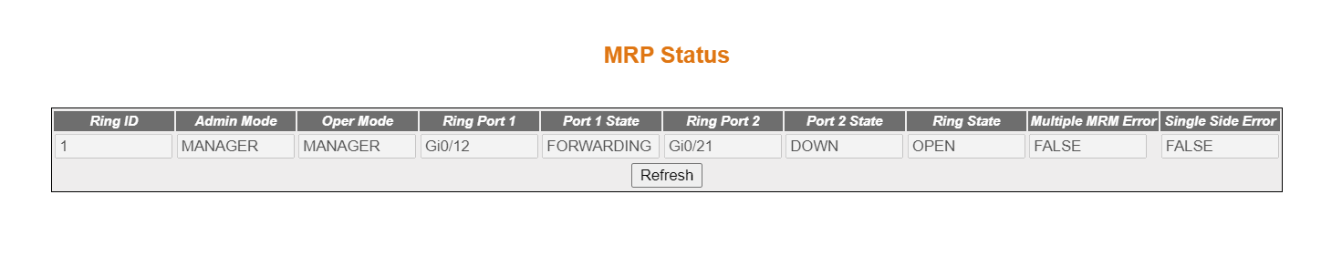
| Screen Objective |
The status of the ring is displayed in the MRP status page. In addition to
the status, the page also displays any errors in the received MRP packets. |
| |
| Navigation |
|
| Fields |
- Ring ID—displays
the Ring ID.
- Admin Mode—displays the admin mode of
the ring.
- Ring Port 1—displays the ring port of
the ring.
- Ring Port 2—displays the ring port of
the ring.
- Port 1 State —displays the port 1 state.
- Port 2 State—displays the port 2 state.
- Ring State—displays the ring state.
- Multiple MRM Error—displays MRM Errors state. This error is
indicated by an MRM when more
than one MRM are active in the
MRP ring. Possible values are as follows:
- false—no multi-MRM error
- true—more than one MRM present
in the ring
- Single Side Error—displays Single Side
Error state. This error also indicated by an MRM when
the test frames of an MRM have
been seen, but only on one ring port.
- false—no one Side
Rx error
- true—test frame received only on one ring port
|
| Buttons |
- Refresh—refreshes
the table.
|