The System Information section allows the user to view
and configure various system properties and settings.
To access System Information screen,
go to .
Figure 1. System Information
By
default, the tab System Information displays
the System Information screen.
System Settings
Figure 2. System Settings
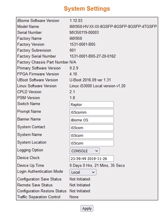
| Screen Objective |
This screen allows the user to configure the
system information. |
| Navigation |
|
| Fields |
- iBiome Software Version—displays
the hardware version number.
- Model Name—displays the hardware configuration
of the system.
- Serial Number—displays the serial number
of the system.
- Factory Name—displays the factory model
name.
- Factory Version—displays the factory
version.
- Factory Subrevision—displays the factory
subrevision.
- Factory Serial Number—displays the mainboard
serial number.
- Factory Chassis Part Number—displays
the factory chassis part number.
- Primary Software Version—displays the
software version number of the system.
- FPGA Firmware Version—displays the FPGA firmware version number.
- U-Boot Software Version—displays the
U-Boot software version number.
- Linux Software Version—displays the Linux
software version number.
- CPLD Version—displays the CPLD version number.
- PSM Version—displays the PSM version
number.
- Switch Name—enter the name for identifying
the device. The default value is iS5. This value range is a string
of size 15.
- Prompt Name—enter the prompt name to
be used. The default value is iS5.
- Banner Name—enter the banner name to
be used. The default value is RAPTOR iBiome Operation System.
- System Contact—enter the contact person
details for this managed node. This value range is a string of size
50. The default value is iS5com.
- System Name—enter the system name. The
default value is iS5com.
- System Location—enter the physical location
of this node. This value range is a string of size 50. The default
value is iS5com.
- Logging Option—select the path to log
the debug details. The default option is Console. The list contains:—
select the current date and time. The format is Day Month Date Year
Hours Minutes Seconds Example: Fri May 07 2010 13: 40: 00.
- CONSOLE—logs
the debug details in a console.
- FILE—logs the debug details in a file (system buffer).
- Device Clock— select the current date
and time. The format is Day Month Date Year Hours Minutes Seconds
Example: Fri May 07 2010 13: 40: 00.
- Device Up Time—displays the time from
which the device is up. The format is Days Hours, Minutes, Seconds
Example: 0 Days 1Hrs, 15Mins, 27 Secs.
|
| Fields (cont) |
- Login Authentication Mode—select
the Login Authentication Mode. The list contains:
- Local —sets
the Authentication Mode as Local. The user identification, authentication,
and authorization method are chosen by the local system administration
and does not necessarily comply with any other profiles
- Remote—sets the Authentication Mode as Remote. Authentication
is done in the remote location through a RADIUS (Remote
Authentication Dial-In User Service) or TACACS server.
RADIUS is a protocol that enables remote access servers to communicate
with a central server to authenticate dial-in users and authorize
their access to the requested system or service. TACACS (Terminal Access Controller
Access-Control System) is a remote authentication protocol that
is used to communicate with an authentication server commonly used
in networks
- tacacs—sets the authentication mode as TACACS.
Authentication is done through a TACACS+
server.
- Configuration Save Status—displays the
configuration save status. The default option is Not Initiated.
Once the configuration is done, the save status will be displayed
as any of the following:
- Successful—system information is
configured and saved successfully.
- Failure—system information configuration Save failed.
- In progress—system information configuration save is in-progress.
- Not Initiated—system information configuration save is not initiated.
- Remote Save Status—displays the remote
save status. The default option is Not Initiated. This status represents
the status of save operation to the remote location as any of the
following:
- Successful—remote information is configured and
saved successfully.
- Failure—remote information configuration Save failed.
- In progress—remote information configuration save is in-progress.
- Not Initiated—remote information configuration save is not initiated.
- Configuration Restore Status—displays
the configuration restore status. The default option is Not Initiated.
The already configured parameter will be restored and the status
will be displayed as any of the following:
- Successful—configuration
is restored successfully.
- Failure—configuration restore failed.
- In progress—configuration restore is in-progress.
- Not Initiated—configuration restore is not initiated.
|
| Fields (cont) |
- Traffic Separation Control—displays
the traffic separation control status. This implies the method for
receiving control packets to CPU.
The default option is None. The options can be:
- System_default—specifies
the method for receiving control packets to CPU as
system default. This implies that the software can automatically install ACL and QoS rules
for all control packets. If the configuration is changed from 'system_default'
to 'user_defined' option, then all default ACL/QoS rules for carrying protocol
control packets to CPU are removed. Then
user has to install the specific ACL/QoS rules, to carry the intended control
packets to CPU for the processing.
- User_defined—specifies the method for receiving control packets
to CPU as user defined. This implies that the software cannot automatically install
the ACL and QoS rules
for all control packets. Only the administrator can install the
required rules for receiving control packets to CPU. If the configuration is changed
from 'user-defined' to system-default or none, all default ACL filters are installed. Already
existing (if any) user configured ACL rules
in the system will be not removed.
- None—specifies the method for receiving control packets to CPUas none.
- If the configuration is changed from 'none' to 'system_default'
option, then all default ACL filters
for carrying protocol control packets to CPU are
removed and new set of filters will be installed. Each filter will
be associated with QoS rules.
If the configuration is changed from 'none' to 'user_defined' option,
then all default ACL filters for
carrying protocol control packets to CPU are
removed. Then user has to install the specific ACL/QoS rules, to carry the intended
control packets toCPU for the processing.
|
| Buttons |
- Apply—logins
to IS5Com and views the Home screen.
|
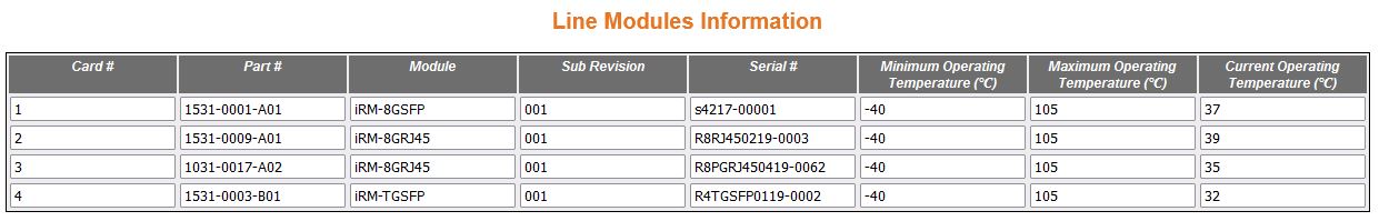
Line Modules Information
Figure 3. Line Modules
Information
| Screen Objective |
This screen allows the user to find information
about the line modules. |
| Navigation |
|
| Fields |
- Card #—displays
card#.
- Part#—displays part number (e.g. 1531-0004-A02)
- Module—displays part number (e.g. iRM-8PGRJ45)
- Sub Revision—displays part number (e.g.
001)
- Serial #—displays the part number (e.g.
R8PGRJ450419-0049)
- Minimum Operating Temperature (C)—displays
minimum temperature (e.g. -40)
- Maximum Operating Temperature (C)—displays
maximum temperature (e.g. 105)
- Current Operating Temperature (C)—displays
current temperature (shown 37)
|
| Buttons |
- Apply—modifies
attributes and saves the changes.
|
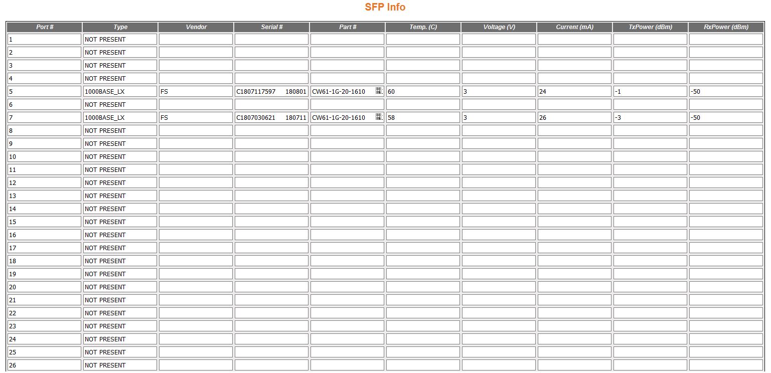
SFP Information
Figure 4. SFP Info
| Screen Objective |
This screen allows the user to find information
about the SFPs. |
| Navigation |
|
| Fields |
- Port #—displays
port#.
- Type#—displays SFP’s
type number.
- Vendor—displays SFP’s
vendor number.
- Serial #—displays SFP’s
serial number.
- Part #—displaysSFP’s
part number.
|
| Fields |
- Temp (C)—displays SFP’s temperature.
- Voltage (V)—displays SFP’s voltage.
- Current (mA)—displays SFP’s current.
- TxPower (dBm)—displays SFP’s TxPower.
- RxPower (dBm)—displays SFP’s RxPower.
|
| Buttons |
- Apply—modifies
attributes and saves the changes.
|
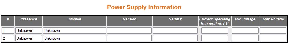
Power Supply Information
Figure 5. Power Supply
Info
| Screen Objective |
This screen allows the user to find information
about the power supplies. |
| Navigation |
|
| Fields |
- Presence—displays
the power supply.
- Module—displays module type.
- Version—displays version.
- Serial #—displays serial number.
- Current Operating Temperature (C)—displays
current temperature
- Min Voltage—displays the minimum voltage.
- Max Voltage—displays the minimum voltage.
|
Clear Counters
Figure 6. Clear counters
| Screen Objective |
This screen allows the user to clear all or
specific health counters. |
| Navigation |
|
| Fields |
- Protocols—select
the protocols for which health check counters is to be cleared.
The options are:
- BGP—clears health check counters for BGP.
- OSPF—clears health check counters for OSPF.
- RIP—clears health check counters for RIP.
- IPv4—clears health check counters for IPv4.
- All—clears all health check counters.
|
| Buttons |
- Apply—modifies
attributes and saves the changes.
|