This section describes how to configure Per VLAN Spanning
Tree Protocol (PVRSTP) on the
switch.
PVRST (Per VLAN
Rapid Spanning Tree) is an enhancement of RSTP,
which works in conjunction with VLAN to
provide better control over traffic in the network. It maintains
a separate spanning tree for each active VLAN in
the network, thus providing load balancing through multiple instances
of spanning tree, fault tolerance, and rapid reconfiguration support
through RSTP.
To access PVRST screens, go to
Global Configuration
By default, the tab Basic
Settings displays the Global Configuration screen.
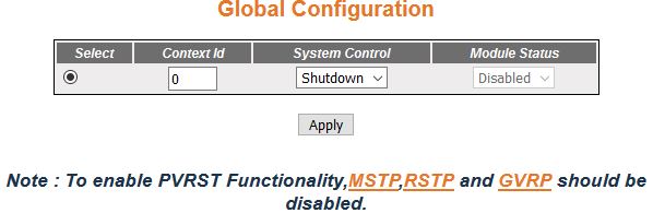
Figure 1. PVRST Global Configuration
| Screen Objective |
This screen allows the user to configure for
each available virtual context the PVRST basic
details that are used globally in the switch for all ports available
in the switch. |
Note: To enable PVRST, the following should be
disabled in the selected context
|
| Navigation |
|
| Fields |
- Select—click
to select the context for which the configuration needs to be done.
|
| Fields (cont) |
- Context ID—displays
the context ID. Currently PVRST can
be enabled only for the Context ID of 0.
- System Control—select the administrative
system control status requested by management for the PVRST. This status allows the
user to set availability of the PVRST feature
on all ports in the switch. The default option is Shutdown. The
list contains:
- Start—specifies that PVRST is
active on all ports of the device. The required memory is allocated
for the feature.
- Shutdown—specifies that PVRST is
shut down on all ports of the device. The allocated memory is released
on all ports.
Note: The system control status can be set
as Start, only if the MSTP System Control is set as Shutdown, RSTP System Control is set as Shutdown,
and Dynamic VLAN Status is set
as Disabled.The system control status can be set as Shutdown, only
if the PVRST Module Status is
set as Disabled. Currently PVRST can
be enabled only for the Context ID of 0.
- Module Status—select the administrative
module status requested by management for the PVRST. The default option is Disabled.
The list contains:
- Enabled—enables the PVRST feature on all ports in
the switch.
- Disabled—disables the PVRST feature
on all ports in the switch.
Note: The module status is
grayed out and cannot be configured, if the PVRST System
Control is set as Shutdown.The module status can be set as Enabled,
only if the PVRST System Control
is set as Start.
|
| Buttons |
- Apply—modifies
attributes for the selected entry and saves the changes.
|
Port Configurations
Figure 2. Port Configurations

| Screen Objective |
This screen allows the user to configure, on
per port basis, the PVRST port
information that is used during computation of loop-free topology. |
Note: The parameters in the screen
are not populated with the values (the screen is blank) if the PVRST System Control status is
set as Shutdown for the context selected using the Context Selection
screen.
|
| Navigation |
|
| Fields |
- Select—click
to select the port for which the configuration needs to be done.
|
| Fields (cont) |
|
| Fields (cont) |
- Disabled—disables BPDU guard feature in the port.
The port state is maintained till is manually enabled
|
| Buttons |
- Apply—modifies
attributes for the selected entry and saves the changes.
|
Instance Bridge Configurations
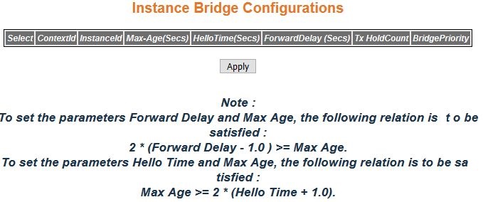
Figure 3. Instance
Bridge Configuration
| Screen Objective |
This screen allows the user to configure bridge
information specific to spanning tree instance, for virtual contexts
available in the switch. This configuration is applied globally
to all ports in the switch. |
Note: The parameters in the screen
are not populated with the values (the screen is blank) if the PVRST System Control status is
set as Shutdown for the context selected using the Context Selection
screen.
|
| Navigation |
|
| Fields |
|
| Fields (cont) |
- Tx HoldCount—enter
the value used by the Port Transmit state machine to limit the maximum
transmission rate. This value is configured to avoid flooding and limit
the maximum transmission rate. This value is from 1 to 10 with default
of 6.
- BridgePriority—enter the priority value
that is assigned to the switch. This is used during the election
of root. This value is from 0 to 61440, the default is 32768.
Note: The
value should be set in increments of 4096; that is, the value can
be set as 0, 4096, 8192, 12288, and so on.The configured priority
is added to the instance ID, and the total value is displayed. For
example, the default priority value is displayed as 32769 if the
instance ID is 1 (32768 + 1).
|
| Buttons |
- Apply—modifies
attributes for the selected entry and saves the changes.
|
Instance Port Configurations
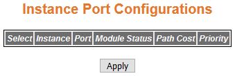
Figure 4. Instance Port
Configurations
| Screen Objective |
This screen allows the user to configure port
specific information for all ports available in the switch on per
port basis. It also allows the user to assign ports to specific instances
so that the instances can make use of the port information. |
Note: The parameters in the screen
are not populated with the values (the screen is blank) if the PVRST System Control status is
set as Shutdown for the context selected at the Context Selection
screen.
|
| Navigation |
|
| Fields |
- Select—click
to select the context for which the configuration needs to be done.
- Instance—displays the spanning tree instance
to which the bridge information belongs. The instance represents
the VLAN ID created in the Static VLAN Configuration screen. For
example, the instance IDs 1 and 3 are displayed if VLAN IDs 1 and 3 are created. This
value ranges from 1 to 4094. The default value is 1.
- Port—displays the port # identifying
a port in the switch- from 1 to 65535.
Note: Only the ports whose
Admin State is set as Up are displayed.
- Module Status—select the administrative
status for the PVRST module.
By default, the value is set same as the value shown in the field
Status in Port Configuration screen. The list contains:
- Enabled—enables PVRST in the device on all ports.
The port participates in the STP process and is ready to transmit/receive BPDUs and data.
- Disabled—disables PVRST in
the device on all ports. The port does not participate in the STP
process and is not ready to transmit/receive BPDUs
/ data.
|
| Fields (cont) |
Note: The module status can be set as Enabled,
only if the Status in Port Configuration is set as Enabled.
- Path Cost—enter the administratively
assigned value for the contribution of this port to the path cost
of paths toward the spanning tree root. The path cost represents
the distance between the root port and designated port. The path
cost is used during calculation of shortest path to reach the root.
This value ranges from 0 to 200000000. The default value is 200000
for all physical ports and 199999 for port channels.
Note: The
configured value is applied, only if the Status in Port Configuration
is set as Enabled.
- Priority—enter
the priority value that is assigned to the port. The four most significant
bits of the port identifier for a given spanning tree instance can
be modified independently for each spanning tree instance supported
by the bridge. This value is used during the port role selection
process. This value ranges from 0 to 240. The values that are set
for Port Priority must be in steps of 16. The default value is 128.
Note: The
configured value is applied, only if the Status in Port Configuration
is set as Enabled.
|
| Buttons |
- Apply—modifies
attributes for the selected entry and saves the changes.
|
Instance Port Status
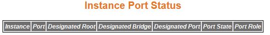
Figure 5. Instance Port Status
| Screen Objective |
This screen allows the user to view information
maintained by every port of the switch for PVRST. |
Note: The parameters in the screen
are not populated with values (the screen is blank) if the PVRST System Control status is
set as Shutdown for the context selected using the Context Selection
screen.
|
| Navigation |
|
| Fields |
- Instance—displays
the spanning tree instance to which the bridge information belongs.
The instance represents the VLAN ID
created in the Static VLAN Configuration
screen. For example, the instance IDs 1 and 3 are displayed if VLAN IDs 1 and 3 are created. This
value ranges from 1 to 4094. The default value is 1.
- Port—displays the port number that uniquely
identifies the specific port in the switch. This value ranges from
1 to 65535.
Note: Only the ports whose Admin State is set as
Up are displayed.
|
| Fields (cont) |
- Designated Root—displays
the unique identifier of the bridge recorded as the instance root
in the transmitted configuration BPDUs.
This value is an 8-byte octet string. For example, 80:01:00:01:02:03:04:01.
- Designated Bridge—displays the unique
identifier of the bridge, which the port considers to be the designated
bridge for the port's segment. The designated bridge is the only
bridge allowed to forward frames to and from the segment. This value
is an 8-byte octet string. For example, 80:01:00:01:02:03:04:01.
- Designated Port—displays the ID of the
port on the Designated Bridge for the port's segment. This represents
the port through which the Designated Bridge forwards frames to
and from the segment. This is a 2-byte octet string (e.g. 80:05).
- Port State—displays the current state
of the port state as defined by the STP. The port states are:
- Disabled—specifies
that the port is disabled manually (PVRST Module Status)
or automatically (Link). The port does not take part in the spanning tree
process.
- Discarding—specifies that the port is in the Discarding state
i.e. no user data is sent over the port.
- Learning—specifies that the port is in Learning state i.e. the
port is not forwarding frames yet, but it is populating its MAC-address-table by learning source
addresses from received frames and storing them in the switching database
for using them while sending and receiving data.
- Forwarding—specifies that the port is in the Forwarding state
i.e. the port is operational by sending and receiving data based
on the formed spanning tree topology which is loop free.
- Port Role—displays the current role of
the port for the spanning tree instance. The port roles are:
- Disabled—specifies
that the port is disabled manually (PVRST Module Status)
or automatically (Link). The port does not take part in the spanning tree
process.
- Alternate—specifies that the port is acting as an alternate
path to the root bridge which is blocked and not used for traffic.
If the root port is blocked, the alternate port is enabled and declared
as a root port.
- Backup—specifies that the port is acting as a backup path to
a segment to which another bridge port already connects and which
is blocked and not used for traffic. If the active designated port
is blocked, the backup drive is enabled and declared as a designated
port.
- Root—specifies that the port is used to forward data to root
bridge directly or through an upstream LAN segment.
- Designated—specifies that the port is used to send to and receive
packets from a specific downstream LAN segment/device. Only one
designated port is assigned for each segment.
|