This section describes the configuration options for
the Open Shortest Path First (OSPF)
routing protocol.
OSPF (Open
Shortest Path First) is an Interior Gateway Protocol used to distribute
routing information within a single Autonomous System. Routers use
link-state algorithms to send routing information to all nodes in
an inter-network by calculating the shortest path to each node based
on topography of the Internet constructed by each node. Each router
sends that portion of the routing table (keeps track of routes to
particular network destinations), which describes the state of its
own links, and it also sends the complete routing structure (topography).
The
advantage of shortest path first algorithms is that they result
in smaller more frequent updates everywhere. They converge quickly,
thus preventing such problems as routing loops and Count-to-Infinity
(when routers continuously increment the hop count to a particular
network). This makes for a stable network.
To access OSPF screens, go to .
OSPF VRF Creation
By
default, the tab OSPF VRF Creation displays screen.
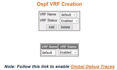
Figure 1. OSPF VRF Creation
| Screen Objective |
This screen allows the user to enable or disable OSPF for the specified VRF instance. |
| Navigation |
|
| Fields |
- VRF Name—default.
- VRF Status—select the admin status of OSPF virtual context. The default option
is Disabled. The list contains:
- Enabled—enables OSPF in the virtual context.
- Disabled—disables OSPF in
the virtual context.
|
| Buttons |
- Add—adds and
saves new configuration.
Note: Status cannot be disabled using
this option.
- Delete—delete the selected entry.
Note: Entry
can be deleted only when the VRF status
is configured as disabled.
|
Debug Trace Settings
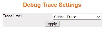
Figure 2. Debug Trace Settings
| Screen Objective |
This screen allows the user to set the debug
trace level. |
| Navigation |
Click Debug
Trace Settings.
|
| Fields |
- Trace Level—select
the level of trace required for OSPF.
The list contains:
- High-Level-Trace—generates debug statements for Packet
High Level Dump trace.
- Low-level-Trace—generates debug statements for Packet Low Level Dump
trace.
- Hex-Dump-Trace—generates debug statements for Packet Hex Dump trace.
- Critical-Trace—generates debug statements for Critical trace.
- Func-entry-Trace—generates debug statements for Function Entry trace.
- Func-exit-Trace—generates debug statements for Function Exit
trace.
- Memory-Success-Trace—generates debug statements for Memory Allocation
Success Trace.
- Memory-Failure-Trace—generates debug statements for Memory Allocation
Failure Trace.
- Hello-pkt—generates debug statements for Hello packet Trace.
- DDP—generates debug statements for DDP packet Trace.
- LRQ—generates debug statements for Link State Request Packet
Trace.
- LSU—generates debug statements for Link State Update Packet
Trace.
- LS-ACK—generates debug statements for Link State Acknowledge Packet
Trace.
- ISM—generates debug statements for Interface State Machine Trace.
- NSM—generates debug statements for Neighbor State Machine Trace.
- RTC-TRACE—generates debug statements for Routing Table Calculation
Trace.
- RTM Module-Trace—generates debug statements for RTM Module Trace.
- Interface-Trace—generates debug statements for Interface Trace.
- NSSA Trace—generates debug statements for NSSA Trace.
- Route-aggregation Trace—generates debug statements for Route Aggregation
Trace.
- Configuration-Trace—generates debug statements for Configuration Trace.
|
| Fields (cont) |
- Trace Level—the
list contains (cont):
- Adjacency—generates debug statements for Adjacency formation Trace.
- LSDB—generates debug statements for Link State Database Trace (LSDB).
- Protocol pkt processing—generates debug statements for Protocol Packet
Processing Trace.
|
| Buttons |
- Add—modifies
attributes for the selected entry and saves the changes.
|
OSPF Basic Settings
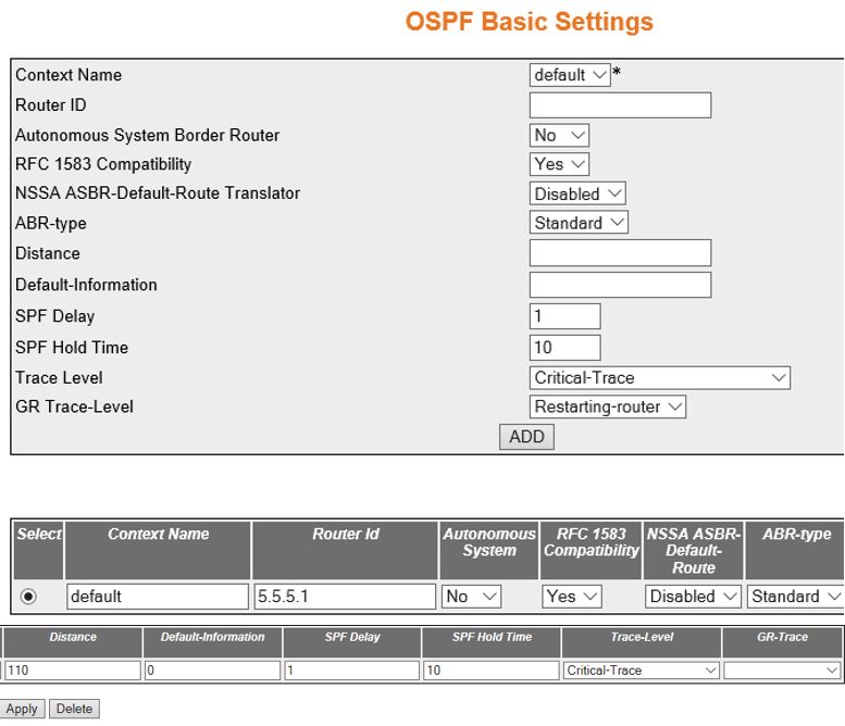
Figure 3. OSPF Basic Settings
| Screen Objective |
This screen allows the user to configure the
basic settings of OSPF. |
| Navigation |
|
| Fields |
- Select—click
to choose the Context Name for which configuration needs to be modified
or deleted.
- Context Name—default.
- Router ID—enter a 32-bit integer that
uniquely identifies the originating router in the AS.
- Autonomous System Border Router/ Autonomous System—select
the status of an ASBR (AS Border
Router). The default option is Yes. The list contains:
- Yes—configures
the router as an ASBR.
- No—configures the router within AS.
- RFC 1583 Compatibility—select the compatibility
status of RFC 1583 or RFC 2178. This controls the preference rules,
when choosing among multiple AS external LSAs
advertising the same destination. The default option is Yes. The
list contains:
- Yes—sets the preference rules to those specified
by the RFC 1583.
- No—sets the preference rules to those specified by the RFC 2178.
- NSSA ASBR Default Route Translator/ NSSA ASBR Default
Route—select the status of the P-Bit setting for the
default Type-7 LSA (Link State
Advertisement) generated by NSSA internal
ASBR, which is not ABR (Area Border
Router)). The default option is Disabled. The list contains:
- Enabled—sets
the P-Bit in the generated Type-7 default LSA.
- Disabled—clears the P-Bit in the generated default LSA.
- ABR Type—select the type of ABRs supported. The default option
is Standard. The list contains:
- Standard—chooses the ABR type as Standard.
- CISCO— chooses the ABR type
as CISCO.
- IBM— chooses the ABR type
as IBM.
- Distance—enter the administrative distance
(the metric to reach destination) of the routing protocol. This
value ranges from 1 to 255. The default value is 0. The value 0
represents the directly connected route.
Note: The administrative
distance can be enabled for only one route map. The distance should
be disassociated from the already associated route map if distance
needs to be associated for another route map.
- Default Information—enter the default
information that is to be used for configuring the OSPF basic settings.
This value ranges from 0 to 65535.
|
| Fields (cont) |
- SPF Delay—configures
the interval by which SPF calculation is delayed after a topology
change reception. This value ranges from 0 to 65535 seconds. The default
value is 1.
- SPF Hold Time—configures the minimum
time between two consecutive SPF calculations. This value ranges
from 0 to 65535 seconds. The default value is 10.
- Trace Level—select the level of trace
required for OSPF. The list contains:
- Packet High Level Dump
Trace—generates debug statements for Packet High Level Dump trace.
- Packet Low Level Dump Trace—generates debug statements for Packet
Low Level Dump trace.
- Packet Hex Dump Trace—generates debug statements for Packet
Hex Dump trace.
- Critical Trace—generates debug statements for Critical trace.
- Function Entry Trace—generates debug statements for Function
Entry trace.
- Function Exit Trace—generates debug statements for Function
Exit trace.
- Memory Allocation Success Trace—generates debug statements for Memory
Allocation Success Trace.
- Memory Allocation Failure Trace—generates debug statements for
Memory Allocation Failure Trace.
- Hello packet Trace—generates debug statements for Hello packet
Trace.
- DDP packet Trace—Generates debug statements for DDP packet Trace.
- Link State Request Packet Trace—generates debug statements for
Link State Request Packet Trace.
- Link State Update Packet Trace—generates debug statements for
Link State Update Packet Trace.
- Link State Acknowledge Packet Trace—generates debug statements
for Link State Acknowledge Packet Trace.
- Interface State Machine Trace—generates debug statements for
Interface State Machine Trace.
- Neighbor State Machine Trace—generates debug statements for
Neighbor State Machine Trace.
- Routing Table Calculation Trace—generates debug statements for
Routing Table Calculation Trace.
- RTM Module Trace—generates debug statements for RTM Module Trace.
|
| Fields (cont) |
- Trace Level—the
list contains (cont):
- Interface Trace—generates debug statements
for Interface Trace.
- NSSA Trace—generates debug statements for NSSA Trace.
- Route Aggregation Trace—generates debug statements for Route
Aggregation Trace.
- Configuration Trace—generates debug statements for Configuration Trace.Adjacency
formation Trace—generates debug statements for Adjacency formation
Trace.Link State Database Trace—Generates debug statements for Link
State Database Trace.
- Protocol Packet Processing Trace—generates debug statements
for Protocol Packet Processing Trace.
- GR Trace-Level—select the graceful restart
trace level for OSPF. The list
contains:
- Restarting-router—generates debug statements for
messages related to restarting router.
- Helper—generates debug statements for messages related to router
in helper Mode.
- Redundancy—generates debug statements for redundancy messages.
|
| Buttons |
- ADD—adds and
saves new configuration.
- Apply—modifies attributes for the selected
entry and saves the changes
- Delete—delete the selected entry.
|
OSPF Area Configuration
Figure 4. OSPF Area Configuration

| Screen Objective |
This screen allows the user to configure the
parameters of the router’s attached areas. |
| Navigation |
|
| Fields |
- Context Name—default.
- Area ID—enter the IP Address that uniquely
identifies an area that is associated with the OSPF address range for which authentication
is to be enabled.
- Type—select the required type for an
area. The default option is Normal. The list contains:
- Normal—allows
all external LSAs (Type 5 LSA) to be flooded through the area.
- Stub—does not allow the external LSA to
be flooded into the area.
- NSSA—allows only limited number of Type 5 external LSA to be translated into Type 7 LSA and flooded into the area.
- Metric / Stub Metric—enter the metric
value applied at the indicated type of service. This is applicable
to stub and NSSA area. This value
ranges from 0 to 16777215. The default value is 10.
Note: This
field is enabled only when Type is set as “NSSA”
and Send Summary routers is set as “Yes”.
- Metric Type/ Stub Metric Type—select
the type of metric advertised as a default route. This is applicable
to stub and NSSA area. The default
option is ospfMetric. The list contains:
- ospfMetric—sets
the metric type as ospfMetric.
- comparableCost—sets the metric type as comparable cost.
- nonComparable—sets the metric type as noncomparable.
Note: This
field is enabled only when Type is set as “NSSA”
and Send Summary routers is set as “Yes”.
- Type of Service / TOS—enter the type
of service associated with the metric. This is applicable to stub
and NSSA area. The default value is 0.
Note: This field is enabled
only when Type is set as “NSSA”
and Send Summary routers is set as “Yes”.
- Translator Role—select an NSSA border router’s ability to
perform NSSA translation of Type-7 LSAs
to Type-5 LSAs. The default option
is Candidate. The list contains:
- Always—sets the translator
role as always to perform NSSA translation of
Type-7 LSAs to Type-5 LSAs.
- Candidate—sets the translator role as candidate to perform NSSA translation of Type-7 LSAs to Type-5 LSAs
- NSSA Translator Stability Interval/ Stability Interval—enter
the number of seconds after which an elected translator determines
that its services are no longer required. This value ranges from
0 to 2147483647. The default option is 40 seconds.
- SPF Run Count—displays the shortest path
first (SPF) run count. The Run Count depends upon the metric type
value. This value ranges from 0 to 65535. This field is greyed out.
|
| Buttons |
- ADD—adds and
saves new configuration.
- Reset—resets to default value for respective
fields and discards all user inputs.
- Apply—modifies attributes for the selected
entry and saves the changes
- Delete—delete the selected entry.
Note: An
auto generated entry cannot be deleted.
|
OSPF Interface Configuration
Figure 5. OSPF Interface
Configuration

| Screen Objective |
This screen allows the user to configure an OSPF for the specified interface. |
| Navigation |
|
| Fields |
- Select—choose
the context name for the OSPF Interface
configuration.
- Context Name—default.
- Interface—select the interface index
of the port which are already configured.
Note: VLAN interface
should be created in Layer 3 Management->IP->VLAN Interface Basic
settings.
- Area ID—enter the IP Address that uniquely
identifies an area that is associated with the OSPF address range
for which authentication is to be enabled.
- Priority—enter the priority of the interface,
which is used in the DR (Designated Router)
election algorithm. When two routers attached to a network attempt
to become the designated router, the one with the higher router
priority takes precedence. If there is a tie, the router with the
higher router ID takes precedence. This value ranges from 0 to 255.
The default value is 1.
- Authentication
Type—enter the type of authentication used on the interface.
The default option is None. The list contains:
- None—sets
the authentication type as no password authentication.
- Simple Password—sets the authentication type as Simple password
type authentication.
- MD5—sets the authentication type as Message Digest 5 based authentication.
- SHA-1—sets the authentication type as Secure Hash Algorithm
1 (SHA1) authentication. SHA1 generates Authentication digest
of length 20 bytes.
- SHA-224—sets the authentication type as Secure Hash Algorithm
224 (SHA224) authentication. SHA224 generates Authentication
digest of length 28 bytes.
- SHA-256—sets the authentication type as Secure Hash Algorithm
256 (SHA256) authentication. SHA256 generates Authentication
digest of length 32 bytes.
- SHA-384—sets the authentication type as Secure Hash Algorithm
384 (SHA384) authentication. SHA384 generates Authentication digest
of length 48 bytes.
- SHA-512—sets the authentication type as Secure Hash Algorithm
512 (SHA512) authentication. SHA512 generates Authentication
digest of length 64 bytes.
|
| Fields (cont) |
- MD5 Key ID—enter
the secret key used to create the message digest appended to the OSPF packet if the authentication
type is MD5. This value ranges from 0 to 255.
Note: This field
is inactive when the authentication type is None and Simple Password
- Authentication Key—enter the key required
for authentication, if authentication is enabled on this interface.
Note: This
field is inactive when the authentication type is None.
- Metric—enter the metric of using the
type of service on the interface. This value ranges from 1 to 65535.
The default value is 10.
- Passive—select the interface as passive
or normal. The default option is No. The list contains:
- Yes—sets
the interface as passive.
- No—sets the interface as normal.
- Demand Circuit—select the Demand OSPF procedures that should be
performed on this interface. The default option is No. The list
contains:
- No—demand OSPF procedures
do not perform on the selected interface
- Yes—demand OSPF procedures
perform on the selected interface.
Note: On point-to-point
interfaces, only one end of the demand circuit must be configured
- If Type—select the OSPF interface type.
The default option is broadcast. The list contains:
- Broadcast—specifies
that the network supports many (more than two) attached routers
and has the capability to address a single physical message to all
of the attached routers (broadcast)
- nbma—specifies that the network supports many (more than two)
routers but has no broadcast capability
- point-to-point—sets the network topology to point-to-point type;
this type displays a network of exactly two routers.
- point-to-multipoint—sets the network type to point-to-multipoint
and treats the non-broadcast network as a collection of point-to-point
links.
- Transit Delay—enter the number of seconds
taken to transmit a link state update packet over the interface.
This value ranges from 0 to 3600 seconds. The default option is
1 second.
- Retransmit Interval—enter the number
of seconds between link-state advertisement retransmissions, for
adjacencies belonging to the interface. The retransmit-interval
value is also used while retransmitting database description and
link-state request packets. This value ranges from 0 to 3600 seconds.
The default option is 5.
|
| Fields (cont) |
- Hello Interval—enter
the length of time, in seconds, between the OSPFv3
hello packets to a particular interface (i.e. the length of time,
in seconds, between the Hello packets that the router sends to the
interface). This value ranges from 1 to 65535 seconds. The default
option is 10.
- Dead Interval—enter the time period for
which the router waits for hello packet from the neighbor before
declaring this neighbor down. This value ranges from 0 to 2147483647
seconds. The default option is 40.
- IP Address—displays the IP Address of
the OSPF interface. This is a
read-only field.
- Designated Router—displays the IP Address
of the Designated Router (DR).
This is a read-only field.
|
| Buttons |
- Add—adds and
saves new configuration.
- Reset—resets to default value for respective
fields and discards all user inputs.
- Apply—modifies attributes for the selected
entry and saves the changes
- Delete—delete the selected entry.
|
OSPF Virtual Interface Configuration
Figure 6. OSPF
Virtual Interface Configuration

| Screen Objective |
This screen allows the user to configure an OSPF virtual link and its parameters. Note: In OSPF, all areas must be connected
to a backbone area. If the connection to the backbone is lost, it
can be repaired by establishing a virtual link. Hello-interval and dead-interval
values must be the same for all routers and access servers on a
specific network.
|
| Navigation |
|
| Fields |
- Select—click
to choose the context name for which the OSPF Interface
configuration needs to be done.
- Context Name—default.
- Transit Area ID—enter the 32-bit integer
uniquely identifying an area, which is traversed by the virtual
link
Note: Area ID 0.0.0.0 is used for the OSPF backbone.
- Neighbor Router ID—enter the router ID
of the virtual neighbor.
- Authentication Type—select the type of
authentication used on the interface. The default option is None.
The list contains:
- None—sets the authentication type as no
password authentication.
- Simple Password—sets the authentication type as Simple password
type authentication.
- MD5—sets the authentication type as Message Digest 5authentication.
- SHA-1—sets the authentication type as Secure Hash Algorithm
1 (SHA1) authentication. SHA1 generates Authentication digest of
length 20 bytes.
- SHA-224—sets the authentication type as Secure Hash Algorithm
224 (SHA224) authentication. SHA224 generates Authentication digest
of length 28 bytes.
- SHA-256—sets the authentication type as Secure Hash Algorithm
256 (SHA256) authentication. SHA256 generates Authentication digest
of length 32 bytes.
- SHA-384—sets the authentication type as Secure Hash Algorithm
384 (SHA384) authentication. SHA384 generates Authentication digest
of length 48 bytes.
- SHA-512—sets the authentication type as Secure Hash Algorithm
512 (SHA512) authentication. SHA512 generates Authentication digest
of length 64 bytes.
- MD5 Key ID—enter the secret key used
to create the message digest appended to the OSPF packet if the
authentication type is md5. This value ranges from 1 to 255.
Note: This
field is inactive when the authentication type is None and Simple
Password.
- Authentication
Key—enter the key required for authentication, if authentication is
enabled on this interface.
Note: This field is inactive when the
authentication type is None.
|
| Fields (cont) |
- Hello Interval—enter
the length of time, in seconds, between the Hello packets send on
the interface. This value ranges from 1 to 65535 seconds. The default option
is 10.
- Router Dead Interval—enter the time period
for which the router waits for hello packet from the neighbor before
declaring this neighbor down. This value ranges from 0 to 2147483647
seconds. The default option is 40.
- Transit Delay—enter the number of seconds
taken to transmit a link state update packet over the interface.
This value ranges from 0 to 3600 seconds. The default option is
1 second.
- Retransmit Interval—enter the number
of seconds between link-state advertisement retransmissions, for
adjacencies belonging to the interface. This value ranges from 0
to 3600 seconds. The default option is 5.
|
| Buttons |
- Add—adds and
saves new configuration.
- Reset—resets to default value for respective
fields and discards all user inputs.
- Apply—modifies attributes for the selected
entry and saves the changes
- Delete—delete the selected entry.
|
OSPF Neighbor Configuration
Figure 7. OSPF Neighbor
Configuration

| Screen Objective |
This screen allows the user to configure the
neighbor router and its priority. Note: Neighbor configuration
can be configured only on NBMA or Point-to-Multipoint networks.
These networks can be configured using the Layer 3 Management >
OSPF > Interface > OSPF Interface Configuration
|
| Navigation |
|
| Fields |
- Context Name—default
- Neighbor IP Address—enter the Neighbour
IP address. The priority of the neighbor is defined by the Neighbor
router ID
- Priority / Neighbor Priority—enter the
priority of the neighbor in the designated router election algorithm.
This value ranges from 0 to 255. The default value is 1. A value
of 0 signifies that the neighbor is not eligible to become a designated
router on this particular network.
|
| Buttons |
- Add—adds and
saves new configuration.
- Reset—resets to default value for respective
fields and discards all user inputs.
- Apply—modifies attributes for the selected
entry and saves the changes
- Delete—delete the selected entry.
|
OSPF RRD Route Configuration
Figure 8. OSPF RRD
Route Configuration

| Screen Objective |
This screen allows the user to configure the
neighbor router and its priority. Note: Neighbor configuration
can be configured only on NBMA or Point-to-Multipoint networks.
These networks can be configured using the Layer 3 Management >
OSPF > Interface > OSPF Interface Configuration
|
| Navigation |
|
| Fields |
- Context Name—default
- Destination Network—enter the IP address
of the destination route
- Network Mask—enter the mask for the given
destination route.
- Route Metric / Metric—enter the metric
value applied to the route before it is advertised into the OSPF
domain. This value ranges from 1 to 16777215. The default value
is 10.
- Route Metric Type / Metric Type—select
the metric type applied to the route before it is advertised into
the OSPF domain. The default option is asexttype2. The list contains:
- asexttype1—sets the route metric type as AS-External type 1
before it is advertised.
- asexttype2—sets the route metric type as AS-External type 2
before it is advertised.
- Route Tag—sets the tag type which describes
whether tags will be automatically generated or will be manually
configured. This value ranges from 0 to 4294967295. The default
value is 0.
|
| Buttons |
- Add—adds and
saves new configuration.
- Reset—resets to default value for respective
fields and discards all user input.
- Apply—modifies attributes for the selected
entry and saves the changes
- Delete—delete the selected entry.
|
OSPF Area Aggregation
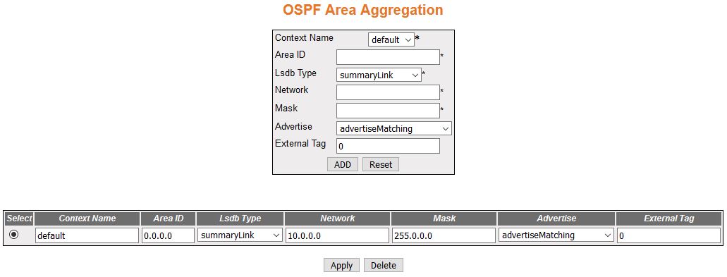
Figure 9. OSPF Area Aggregation
| Screen Objective |
This screen allows the user to configure the
External Tag for configured Type-7 address ranges. |
| Navigation |
|
| Fields |
- Context Name—default
- Area ID—enter the 32-bit integer uniquely
identifying the area in which the address aggregate is to be found
- Lsdb Type—select the Lsdb type of the
address aggregate. The default option is summaryLink. The list contains:
- summaryLink—sets the LSA type
as summary LSA
- nssaExternalLink—sets the LSA type
as NSSA external Link
- Network—enter the IP address of the network
that enables the OSPF routing for interfaces defined and removing
the area ID of that interface. When a more specific OSPF network
range is removed, interfaces belonging to that network range will
be retained and remain active if and only if a less specific network
range exists.
- Mask—enter the Subnet Mask that pertains
to the Net or Subnet for the given destination IPv4 address.
- Advertise—select whether the subnets
are advertised outside the area or not. The default option is advertiseMatching.
The list contains::
- advertiseMatching—allows the subnets
subsumed by ranges to trigger the advertisement of the indicated
aggregate
- doNotAdvertiseMatching—does not advertise subnets outside the
area
- External Tag—enter the External Tag of
the external route. This tag is used to communicate information
between AS boundary routers. The default value is 0.
|
| Buttons |
- Add—adds and
saves new configuration.
- Reset—resets to default value for respective
fields and discards all user input.
- Apply—modifies attributes for the selected
entry and saves the changes
- Delete—delete the selected entry.
|
OSPF AS External Area Aggregation
Figure 10. OSPF
AS External Area Aggregation

| Screen Objective |
This screen allows the user to configure the
Type-5 / Type-7 address ranges specifying whether for the configured
range, Type-5 / Type-7 LSA will
be aggregated or not. |
| Navigation |
|
| Fields |
- Context Name—default
- Network—enter the IP address of the network
that enables the OSPF routing
for interfaces defined and removing the area ID of that interface.
When a more specific OSPF network range is removed, interfaces belonging
to that network range will be retained and remain active if and
only if a less specific network range exists.
- Mask—enter the Subnet Mask for the given
destination IPv4 address
- Area ID—enter the identifier of the area
about which routes are to be summarized. It can be specified as
either a decimal value or as an IP address.
- Aggregation Effect /Advertise—select
whether Type-5/Type-7 will be aggregated or not. The default option
is advertise. The list contains:
- advertise—generates aggregated
Type-5 if the associated Area ID is 0.0.0.0; generates aggregated
Type-7 in the corresponding NSSA area
if Area ID is other than 0.0.0.0
- doNotAdvertise—generates aggregated Type-7 in all attached NSSA areas if the associated Area
ID is 0.0.0.0. Does not generate aggregated Type-7 in the corresponding NSSA area if the Area ID is other
than 0.0.0.0
- allowAll—generates aggregated Type-5 for the specified range
and generates aggregated Type-7 in all attached NSSA areas only if the associated
Area ID is 0.0.0.0. This allowAll option is not valid for Area ID
other than 0.0.0.0.
- denyAll—does not generate Type-5 or Type-7 for the specified
range. This option is not valid for Area ID other than 0.0.0.0
|
| Fields (cont) |
- Translation—select
the P Bit setting in the generated Type-7 LSA.
The default option is enabled. The list contains:
- enabled—sets
P Bit in the generated Type-7 LSA.
- disabled—clears the P Bit in the generated Type-7 LSA.
|
| Buttons |
- Add—adds and
saves new configuration.
- Reset—resets to default value for respective
fields and discards all user input.
- Apply—modifies attributes for the selected
entry and saves the changes
- Delete—delete the selected entry.
|
Graceful Restart Settings
Figure 11. Graceful Restart
Settings
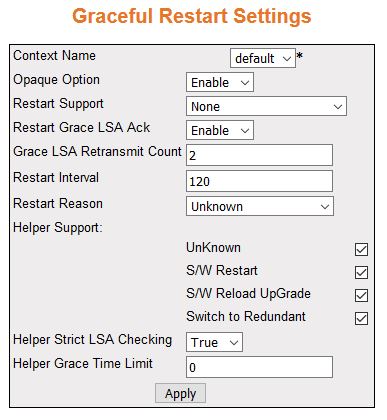
| Screen Objective |
This screen allows the user to configure Graceful
Restart for OSPF. The Graceful
Restart feature allows forwarding of data packets to continue along
known routes, while the routing protocol information is being restored
following a processor switchover. |
| Navigation |
|
| Fields |
- Context Name—default
- Opaque Option—select the opaque-capable
option. The default option is Disable. The list contains:
- Enable—enables
the opaque-capable option.
- Disable—disables the opaque-capable option.
- Restart Support—select the router support
for the OSPF Graceful Restart
feature. The default option is None. The list contains:
- None—does
not restart support of the OSPF Graceful
Restart feature.
- Planned Only—restarts support of the OSPF Graceful
Restart feature only in planned state.
- Planned and Unplanned—restarts of the OSPF graceful
restart feature both in planned and unplanned state.
Note: This
option is enabled only when opaque option is enabled.
- Restart Grace LSA Ack—select whether
the Grace LSAs sent by the router
are expected to be acknowledged by the peers if the Grace Ack Required
state is enabled. The default option is Enable. The list contains:
- Enable—Grace LSAs sent by
the router are acknowledged by the peers.
- Disable—Grace LSAs sent by
the router are not acknowledged.
Note: This option is
enabled only when opaque option is enabled.
- Grace LSA Retransmit Count—enter the
number of retransmissions for unacknowledged Grace LSAs. This value
ranges from 0 to 180. The default value is 2.
Note: This option
is enabled only when opaque option is enabled.
- Restart Interval—enter the OSPF Graceful Restart timeout interval.
This value specifies the Graceful Restart interval, in seconds,
during which the restarting router has to reacquire OSPF neighbors that are fully operational
prior to the Graceful Restart. This value ranges from 1 to 1800.
The default is 120.
Note: This option is enabled only when opaque
option is enabled.
- Restart Reason—select the router Restart
Reason code of the OSPF graceful restart
feature. The default option is Unknown. The list contains:
- UnKnown—restarts
the system due to unplanned events (such as restarting after a crash).
- S/W Restart—restarts the system due to software restart.
- S/W Reload UpGrade—restarts system due to reloading / upgrading
of software.
- Switch to Redundant—restarts system due to switch over to a
redundant support processor.
Note: This option is enabled
only when opaque option is enabled.
|
| Fields (cont) |
|
| Buttons |
- Apply—modifies
attributes for the selected entry and saves the changes
|