BGP (Border Gateway Protocol) is used to build an AS connectivity graph that is used to prune routing loops and enforce policies at AS level.
BGP (Border Gateway Protocol) is an Inter AS (Autonomous Systems) Routing Protocol that manages the distribution of Network Layer Reachability Information (NLRI) across AS.
To access BGP screens, go to .
BGP Creation

| Screen Objective | This screen allows the user to configure the basic settings of BGP. |
| Navigation |
|
| Fields |
|
| Buttons |
|
BGP Basic Settings
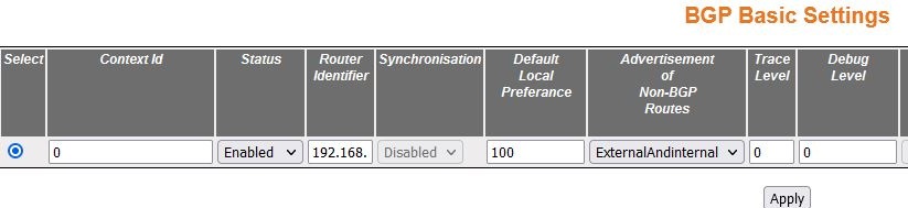
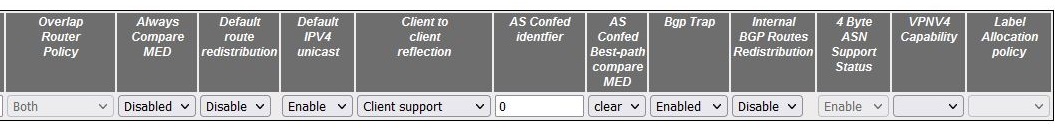
| Screen Objective | This screen allows the user to configure the basic parameters of BGP in the system. |
| Note | To enable BGP, Route Redistribution must be enabled. Use . The BGP system can be enabled and the basic BGP parameters for a context can be configured, only if the local AS Number is configured for the context using the screen. |
| Navigation |
|
| Fields |
|
| Fields (cont) |
|
| Fields (cont) |
|
| Fields (cont) |
|
| Fields (cont) |
|
| Buttons |
|
BGP Settings
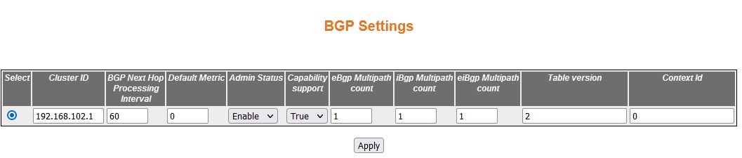
| Screen Objective | This screen allows the user to configure the BGP Settings. |
| Note | This screen can be configured only when the BGP status is enabled using screen. |
| Navigation |
|
| Fields |
|
| Buttons |
|
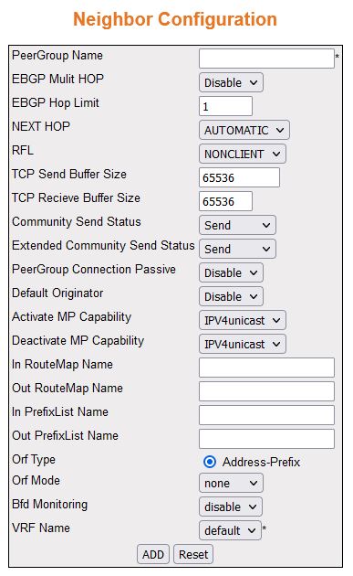
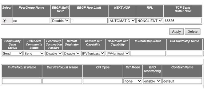
Neighbor Configuration
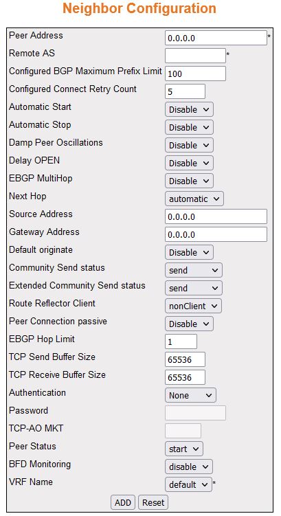
| Screen Objective | This screen allows the user to configure the BGP Neigbors. |
| Note | This screen can be configured only if the Route Re-distribution (RRD) status is enabled with valid ASN and router ID from the . |
| Navigation |
|
| Fields |
|
| Fields (cont) |
|
| Fields (cont) |
|
| Fields (cont) |
|
| Fields (cont) |
|
| Fields (cont) |
|
| Buttons |
|
BGP MED Configuration
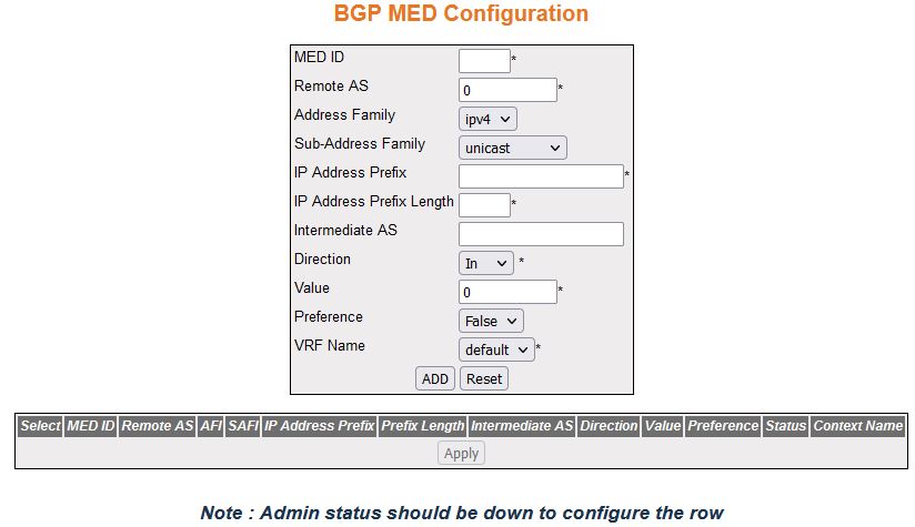
| Screen Objective | This screen allows the user to configure the Multi-Exit Discriminators (MED) values that are to be assigned to routes learnt from BGP peers. |
| Navigation |
|
| Fields |
|
| Fields (cont). |
|
| Buttons |
|
BGP Local Preference Configuration
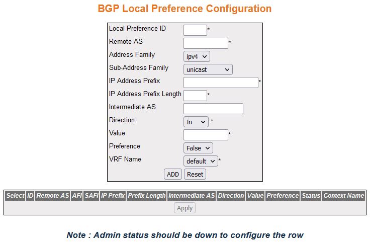
| Screen Objective | This screen allows the user to configure the Local Preference values for the routes. |
| Navigation |
|
| Fields |
|
| Fields (cont) |
|
| Buttons |
|
BGP Filter Configuration

| Screen Objective | This screen allows the user to configure an entry in Update Filter Table which contains rules to filter out updates based on the AS from which they are received, NLRI, and AS through which it had passed. |
| Navigation |
|
| Fields |
|
| Fields (cont) |
|
| Buttons |
|
BGP Route Aggregation Configuration
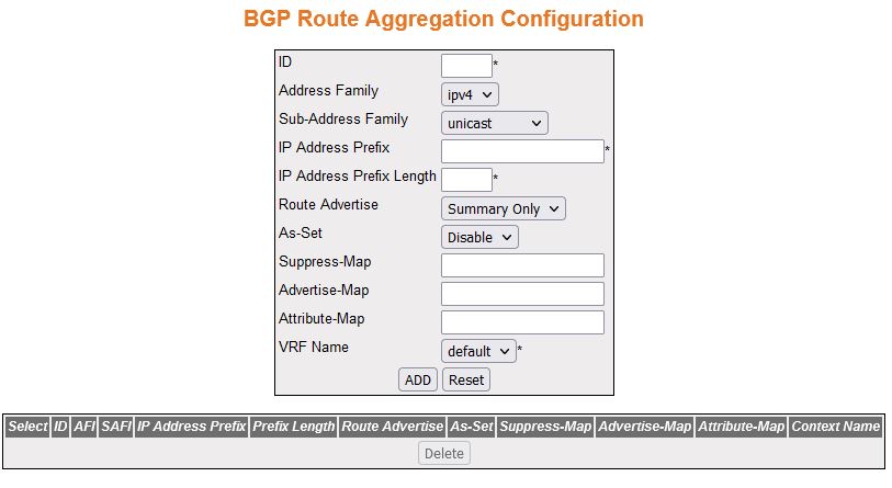
| Screen Objective | This screen allows the user to configure the aggregation of the routing information. This creates an aggregate entry in a BGP or multiprotocol BGP routing table if any more-specific BGP or multiprotocol BGP routes are available that fall in the specified range. The entries in the table specify the IP address based on which the routing information has to be aggregated. The aggregate route will be advertised as coming from autonomous system. The atomic aggregate attribute will be set only if some of the information in the AS PATH is missing in the aggregated route; otherwise, it will not be set. |
| Navigation |
|
| Fields |
|
| Fields (cont) |
|
| Buttons |
|
BGP Timer Configuration
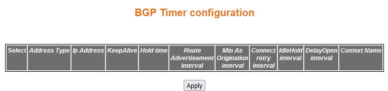
| Screen Objective | This screen allows the user to configure the timer related parameters for the peer. |
| Note | The BGP peer timer entry is created ONLY for the peer entries created in the Neighbor Configuration screen. Generate peer entries before creating BGP Timer configuration. |
| Navigation |
|
| Fields |
|
| Fields (cont) |
|
| Buttons |
|
BGP GR Settings

| Screen Objective | This screen allows the user to configure the Graceful Restart (GR) settings of the BGP. GR capability in a router which allows forwarding of data packets to continue along known routes, while the routing protocol information is being restored following a processor switchover. When GR is enabled, peer networking devices are informed, through protocol extensions prior to the event, of the stateful switch over-capable routers ability to perform GR. When a switch over occurs, the peer will continue to forward to the switching over router as instructed by the GR process for each particular protocol, even though in most cases the peering relationship needs to be rebuilt. Essentially, the peer router will give the switching over router a "grace" period to re-establish the neighbor relationship, while continuing to forward to the routes from that peer. |
| Navigation |
|
| Fields |
|
| Buttons |
|
TCP-AO MKT Configuration
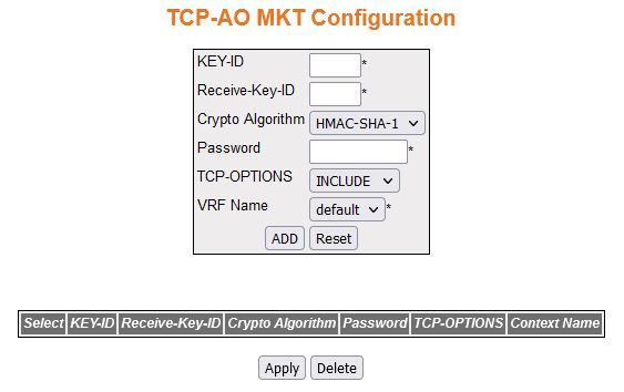
| Screen Objective | This screen allows the user to configure TCP-AO MKT (Authentication Option Master Key Tuple) in the specified BGP instance. |
| Navigation |
|
| Fields |
|
| Fields (cont) |
|
| Buttons |
|
Peer Group Configuration
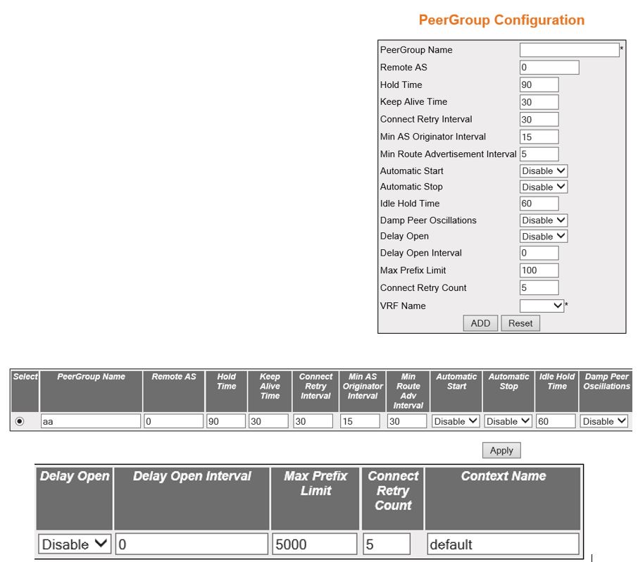
| Screen Objective | This screen allows the user to create a BGP peer group and configure its parameters. The peer group configurations are applicable to all peers present in the peer group. |
| Navigation |
|
| Fields |
|
| Fields (cont) |
|
| Fields (cont) |
|
| Buttons |
|
Neighbor Configuration—Peer Group 2
| Screen Objective | This screen allows the peer group name to configure the parameters for BGP peer associated with the peer group. |
| Navigation |
|
| Fields |
|
| Fields (cont) |
|
| Fields (cont) |
|
| Fields (cont) |
|
| Buttons |
|
Peer Addition
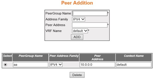
| Screen Objective | This screen allows the user to add a configured peer to a peer group. |
| Note | This screen can be configured only if a peer and a peer group are created.
|
| Navigation |
|
| Fields |
|
| Buttons |
|
Clear BGP
| Screen Objective | This screen allows the user to reset the BGP connection dynamically for inbound and outbound route policy. The inbound routing tables are updated dynamically or by generating new updates using stored update information. |
| Navigation |
|
| Fields |
|
| Fields |
|
| Buttons |
|
BGP Route Map Settings
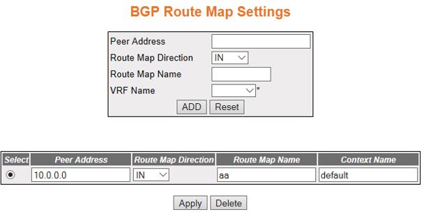
| Screen Objective | This screen allows the user to configure the BGP route map for a neighbor. |
| Note | Route map can be configured only if a neighbor is created using the screen. |
| Navigation |
|
| Fields |
|
| Buttons |
|
Peer Orf Config
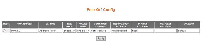
| Screen Objective | This screen allows the user to configure the Outbound Route Filter (ORF) filters. |
| Navigation |
|
| Fields |
|
| Buttons |
|
ORF Filters

| Screen Objective | This screen displays the ORF (Outbound Route Filtering) entries created already in the system. |
| Navigation |
|
| Fields |
|
Filtering
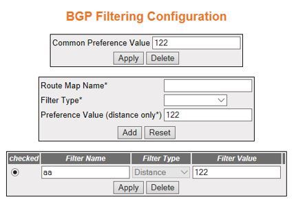
| Screen Objective | This screen displays the BGP Filtering Configuration. |
| Navigation |
|
| Fields |
|
| Buttons |
|