This section describes Protocol Independent Multicast
(PIM) configuration.
PIM (Protocol
Independent Multicast) is a multicast routing protocol designed
to provide scalable inter-domain multicast routing across the Internet. PIM provides multicast routing and
forwarding capability to a router that runs the IP protocol along
with IGMP. PIM supports
a plane-separated architecture for the control and forwarding planes. PIM is independent of the underlying
unicast routing protocol and uses the information from the unicast
routing protocol.
To access PIM screens, go to .
PIM Basic Settings
By default, the tab Basic
Settings displays the PIM Basic Settings screen.
Figure 1. PIM Basic Settings
| Screen Objective |
This screen allows the user to configure the PIM basic settings. |
Note: PIM is
enabled only when IGMP. Proxy
is disabled.
|
| Navigation |
|
| Fields |
- PIM Status—select
the PIM status in the switch.
The default value is Disabled. The list contains.
- Enabled—enables PIM globally in the switch.
- Disabled—disables PIM globally
in the switch.
- PIMv6 Status—select the PIMv6 status in the switch. The
default value is Disabled. The list contains:
- Enabled—enables PIMv6 globally in the switch.
- Disabled—disables PIMv6 globally
in the switch.
- PIM PMBR Status—select the PIM Multicast Border Router (PMBR) Status. A PMBR integrates two different PIM domains (either PIM-SM or PIM-DM) and
also connects a PIM domain to
another multicast routing domain(s). The default value is Disabled.
The list contains:
- Enabled—enables PIM PMBR in the switch.
- Disabled—disables PIM PMBR globally in the switch.
- PIM Router Mode—select the mode of the PIM-SM router. The list contains:
- SSM Only—SSM only mode of the PIM-SM router.
- SM, SSM—SM_SSM mode of the PIM-SM router.
|
| Fields |
Note: This parameter can be set only if PIM is started globally in the switch.
The
family of PIM protocols includes
dense-mode (DM), sparse-mode (SM), source
specific multicast (SSM), and
bidirectional (Bidir) PIM. Bidir PIM is to be used for a many-to-many
applications model.
- PIM Static RP Status—select
the static configuration of RP status.
A rendezvous point (RP) is required
only in networks running PIM-SM.
The protocol is described in RFC 2362. Static configuration allows
additional structuring of the multicast traffic by directing the
multicast join/prune messages to statically configured RPs. The list contains:
- Enabled—enables PIM Static RP Status
in the switch.
- Disabled—disables PIM Static RP Status in the switch.
Note: This
parameter can be set only if PIM is
started globally in the switch.
- PIM Bidir Status—select the static configuration
of RP status. A RP is required only in networks running PIM-SM. The protocol is described
in RFC 2362. Static configuration allows additional structuring
of the multicast traffic by directing the multicast join/prune messages
to statically configured RPs. The
list contains:
- Enabled—enables PIM Bidir Status in the switch.
- Disabled—disables PIM Bidir Status in the switch.
Note: This
parameter can be set only if PIM is started globally in the switch.
- PIM RPF Status—select the PIM RPF (Reverse
Path Forwarding) status in the router. The list contains:
- Enabled—enables PIM RPF Status
in the switch.
- Disabled—disables PIM RPF status in the switch.
Note: This
parameter can be set only if PIM is
started globally in the switch.
|
| Buttons |
- Apply—modifies
attributes and saves the changes.
|
PIM Component Configuration
Figure 2. PIM Component Configuration
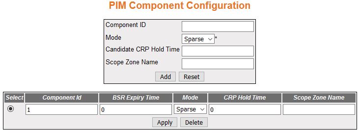
| Screen Objective |
This screen allows the user to configure the PIM component parameters. |
| Navigation |
|
| Fields |
- Select—click
the Component ID value for which parameters are to be reapplied.
- Component ID—enter a unique number to
configure the PIM component in the
router. The PIM component corresponds to each instance of a PIM domain and classifies it as
Sparse or Dense mode. This value ranges from 1 to 255.
- Mode—select the operating mode for the
configured component ID. The default option is Sparse. The list
contains:
- Dense—indicates the component is running in Dense
mode, implicitly building shortest-path trees by flooding multicast
traffic domain wide, and then pruning back branches of the tree
where no receivers are present.
- Sparse—indicates the component is running in Sparse mode, explicitly building
unidirectional shared trees rooted at an RP per
group, and optionally creates shortest-path trees per source.
- Candidate CRP Hold Time/ CRP Hold Time—enter
the hold time of the component when it is a candidate RP in the local domain. This value
ranges from 0 to 255. The default value is 0.
- BSR Expiry Time—displays
the minimum time remaining before the bootstrap router in the local
domain is declared down. This is a read-only field.
Note: For
candidate BSRs (Bootstrap Routers),
the expiry time is the time until the component sends an RP-set message.For other routers,
the expiry time is the time until the component is accepting an RP-set message from a lower candidate BSR.
|
| Fields (cont) |
- Scope Zone Name—enter
the Scope Zone Name. The maximum length of the string is 64.
Note: Scope
is a 4-bit value that describes the scope of an IPv6 address. A unicast
address can possibly have 2 scopes (Linklocal and Global) only,
and a multicast address can have a maximum of 11 scopes. The Scope
Zone Name should be the same as that of the zone created in the
ipv6 scope zone command. If ipv6 scope-zone is created as scopeA1,
then the scope zone name should be scopeA1. (note that the string
is without space).
|
| Buttons |
- Add—adds and
saves new configuration.
- Reset—resets to default value and discards
all user input.
- Apply—modifies attributes and saves the
changes.
- Delete—deletes the selected entry.
|
PIM Interface Configuration
Figure 3. PIM Interface Configuration

| Screen Objective |
This screen allows the user to configure the PIM component parameters. |
| Navigation |
|
| Fields |
- Select—click
the interface for which PIM interface
parameters are to be reapplied.
- Interface—select the index value of the PIM interface.
- Address Type—specifies the address type
of the PIM interface. The available
option is IPv4.
- Address—displays the IP address.
|
| Fields (cont) |
- Mask Length—displays
the IP mask length for the configured IP address. This value ranges
from 0 to 32 for an IPv4 address.
- DR Address—displays the DR (Designated Router) address.
- Hello Interval—enter the frequency at
which PIM Hello messages are transmitted.
This value ranges from 1 to 255 seconds with a default of 30 secs.
- Join Prune Interval—enter frequency at
which PIM Join/Prune messages are
transmitted. The value is from 1 to 255 secs and a default of 60
secs.
- C-BSR Preference—enter
the preference value for the local interface as a C-BSR. This value ranges from 1 to
255. The default value is 1.
- Component ID—to configure the PIM component, enter an unique number, which
corresponds to each instance of a PIM domain
and classifies it as Sparse or Dense mode. This value is from 1
to 255.
|
| Buttons |
- Add—adds and
saves new configuration.
- Reset—resets to default value and discards
all user input.
- Apply—modifies attributes and saves the
changes.
- Delete—deletes the selected entry.
|
PIM Candidate RP Configuration
Figure 4. PIM Candidate
RP Configuration
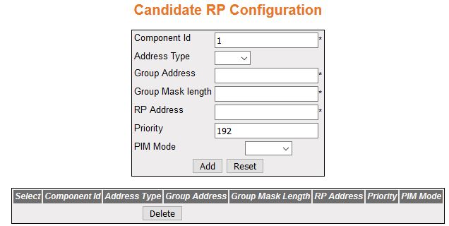
| Screen Objective |
This screen allows the user to configure PIM information for a Candidate RP for IP multicast groups. A Candidate RP is a router configured to send
periodic Candidate-RP-Advertisement messages to the candidate Bootstrap
Router (BSR), and processes Join/Prune
or Register messages for the advertised group prefix, when it is elected
as RP. |
Note: To configure this screen:
- PIM module is enabled globally.
- PIM mode is set as sparse.
- PIM query interval and IP
address must be configured.
|
| Navigation |
|
| Fields |
- Select—click
the Component ID value for which parameters to be reapplied.
- Component ID—to configure the PIM component, enter an unique number, which
corresponds to each instance of a PIM domain
and classifies it as Sparse or Dense mode. This value is from 1
to 255.
- Address Type—specifies the address type
of the PIM interface. The available option
is IPv4.
- Group Address—enter the IP multicast
group address, for which the switch advertises itself as Candidate
RP which contains the multicast routing information.
- Group Mask Length—enter the subnet mask,
which when combined with the group address gives the group prefix.
This value ranges from 0 to 32 for IPv4.
- RP Address—enter the IP address of the
Candidate RP.
- Priority—enter the priority of the Candidate RP. The priority value ranges from
0 to 255. The default value is 192.
- PIM Mode—select PIM Mode of the group
for which the Candidate RP is configured.
The list contains:
- Sparse—specifies that the Candidate RP is running in Sparse mode.
- Bidir—specifies that
the Candidate RP is running in Bidir mode.
Note: To
set PIM Mode as Bidir, Bidirectional PIM should be enabled in PIM Basic Settings screen (Multicast
> PIM)
|
| Buttons |
- Add—adds and
saves new configuration.
- Reset—resets to default value and discards
all user input.
- Delete—deletes the selected entry.
|
PIM Static RP Configuration
Figure 5. PIM Static RP
Configuration

| Screen Objective |
This screen allows the user to configure PIM information for static RP for IP multicast groups. |
Note: To configure this screen:
- PIM module is enabled globally.
- PIM mode is set as sparse.
|
| Navigation |
|
| Fields |
- Select—click
the Component ID value for which parameters to be reapplied.
- Component ID—enter a unique number to
configure the PIM component in
the router. The PIM component corresponds to each instance of a PIM domain and classifies it as
Sparse or Dense mode. This value ranges from 1 to 255.
- Address Type—specifies the address type
of the PIM interface. The available option
is IPv4.
- Group Address—enter the IP multicast
group address, for which the switch advertises itself as Candidate RP which contains the multicast routing
information.
- Group Mask Length—enter the subnet mask,
which when combined with the group address gives the group prefix.
This value ranges from 0 to 32 for IPv4.
- RP Address—enter the IP address of the
Static-RP.
- Embedded RP—select the status of the
Embedded RP. The default option
is Disable. The list contains:
- Enable—enables the Embedded RP feature.
- Disable—disables the Embedded RP feature
Note: To
set PIM Mode as Bidir, Bidirectional
PIM should be enabled in PIM Basic Settings screen (Multicast >
PIM)
|
| Fields |
- PIM Mode—select PIM Mode of the group for which
the Candidate RP is configured.
The list contains:
- Sparse—specifies that the Candidate RP is running in Sparse mode.
- Bidir—specifies that
the Candidate RP is running in
Bidir mode.
Note: To set PIM Mode as Bidir, Bidirectional PIM should be enabled in PIM Basic Settings screen (Multicast
> PIM)
|
| Buttons |
- Add—adds and
saves new configuration.
- Reset—resets to default value and discards
all user input.
- Apply—modifies attributes and saves the
changes.
- Delete—deletes the selected entry.
|
PIM Global Configuration
Figure 6. PIM Global Configuration

| Screen Objective |
This screen allows the user to configure the PIM component parameters. |
Note: To configure this screen:
- PIM module is enabled globally.
- PIM mode is set as sparse.
|
| Navigation |
|
| Fields |
- Offer Interval—enter
the time interval between the Designated Forwarder (DF) election
Offer messages to be sent. The default value is 100 milli seconds.
This value ranges from 1 to 20000000 milliseconds.
- Offer Limit—enter the Bidir-PIM Offer Limit, the
number of unanswered offers before the router changes as the DF,
which is a value in the range from 3 to 100. The default value is
3.
|
| Fields (cont) |
- Group Threshold—enter
a BPS (Bits-per-second) value
that initiates the source specific counters for a particular group
when the threshold of data rate for any group is exceeded. It is
based on number of packets. The default value is 0. This value ranges
from 0 to 2147483647.
- Source Threshold—enter a BPS value that initiates the switching
to shortest path tree when the threshold of data rate or the number
of packets for any source is exceeded. It ranges from 0 to 2147483647.
The default value is 0.
- Switching Period—enter the time period
(in seconds) over which the data rate is to be monitored for switching
to shortest path tree. The default value is 0. This value ranges
from 0 to 2147483647.The same period is used for monitoring the
data rate for both source and group. To switch to shortest path
tree (SPT), this period must be
configured. The SPT is used for
multicast transmission of packets with the shortest path from sender
to recipients.
- RP Threshold—enter the threshold at which
the RP initiates switching to source
specific shortest path tree. This value ranges from 0 to 2147483647. This
value ranges from 0 to 2147483647. The default value is 0. To switch
to SPT, this threshold must be
configured, and the switching is based on the number of registered
packets received
- RP Switching Period—enter the time period
(in seconds) over which RP monitors
register packets for switching to the source specific shortest path tree.
The default value is 0. This value ranges from 0 to 2147483647. RP-tree is a pattern in which multicast
packets are sent to a PIM-SM router
by unicast and then forwarded to actual recipients from RP to switch to SPT; this period must be configured.
|
| Buttons |
- Apply—modifies
attributes and saves the changes.
|
PIM DM Global Configuration
Figure 7. PIM Global
Configuration
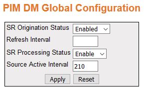
| Screen Objective |
This screen allows the user to configure the PIM component parameters. |
Note: This screen displays
only if PIM module is enabled
globally.
|
| Navigation |
|
| Fields |
- SR Origination Status—select
the Origination Status of the State Refresh (SR)
message. The default option is Disabled. The list contains:
- Disabled—does
not generate the SR message.
- Enabled—generates the SR message.
- Refresh Interval—enter the interval between
origination and sending out of successive SRM (State
Refresh Messages) control messages by the router. This value ranges
from 4 to 100.
- SR Processing Status—select
the processing status of a SR message.
The default value is Disable. The list contains:
- Disable—disables
the processing and forwarding of a SRM,
that is, the router drops the SRM if
received. In addition, the router will not advertise the SR capability in Hello messages.
- Enable—enables the SRM processing
and forwarding. On enabled, this router advertises itself as SR-capable in Hello messages.
- Source Active Interval—enter the time
period (in seconds) for which the SR control
messages are generated by the router after a data packet is received.
The default value is 210 seconds. This value ranges from 120 to 210
seconds.
|
| Buttons |
- Add—adds and
saves new configuration.
- Reset—resets to default value and discards
all user input.
|
PIM Route Configuration
Figure 8. PIM Route Configuration
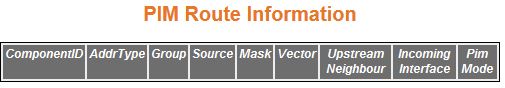
| Screen Objective |
This screen allows the user to configure the PIM component parameters. |
| Navigation |
|
| Fields |
- Component ID—enter
a unique number to configure the PIM component. The
PIM component corresponds to each instance of a PIM domain and classifies it as
Sparse or Dense mode. This value ranges from 1 to 255.
- Address Type—specifies the address type
of the PIM interface— IPv4.
- Group—displays the IP multicast group
address for which the multicast routing information is displayed.
- Source—displays the network address of
the source.
- Mask—displays the network mask of the
source.
|
| Fields (cont) |
- Vector—displays PIM Reverse Path Forwarding vector
(RPF) value.
- Upstream Neighbour—displays the address
of the upstream neighbor from which IP datagram sent to the multicast
address are received
- Incoming Interface—specifies the value
of IfIndex (Upstream Interface Configuration) for the interface
on which IP datagram sent to the multicast address are received.
This is a read-only field.
- PIM Mode—select PIM Mode
of the group for which the Candidate RP is configured.
The list contains:
- Sparse—specifies that the Candidate RP is running in Sparse mode.
- Bidir—specifies that
the Candidate RP is running in Bidir mode.
|
PIM RP Configuration
Figure 9. PIM RP Configuration
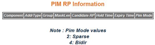
| Screen Objective |
This screen displays the PIM information for
candidate RPs for IP multicast groups.
The PIM information is obtained
from received candidate RP advertisements, if the local router is BSR. The PIM information is obtained
from received RP set messages if
the local router is not BSR. |
Note: This screen displays
only if PIM module is enabled globally.
|
| Navigation |
|
| Fields |
- Component ID—enter
a unique number to configure the PIM component. The
PIM component corresponds to each instance of a PIM domain and classifies it as
Sparse or Dense mode. This value ranges from 1 to 255.
- Address Type—specifies the address type
of the PIM interface—IPv4.
- Group—displays the IP multicast group
address for which the information about the candidate RP is displayed.
- Mask Length—displays the multicast group
address mask.
- Candidate RP—displays the IP address
of the Candidate RP.
- Hold Time—displays the time remaining
for the advertisement of a Candidate RP to
be aged out. This value range is from 0 to 255 seconds. This value is
0 for the local router that is not configured as BSR.
|
| Fields |
- Expiry Time—displays
the minimum time remaining for the candidate RP to be
declared as down. This value is 0 for the local router that is BSR.
- PIM Mode—select PIM Mode of the group
for which the Candidate RP is configured.
The list contains:
- Sparse—specifies that the Candidate RP is running in Sparse mode.
- Bidir—specifies that
the Candidate RP is running in Bidir mode
|
PIM High Availability
Figure 10. PIM High Availability
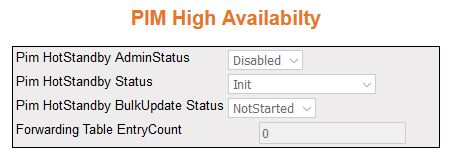
| Screen Objective |
This screen displays the PIM High
Availability (HA) information for
IP multicast groups. |
Note: This screen displays
only if PIM module is enabled
globally.
|
| Navigation |
|
| Fields |
- PIM Hot Standby Admin Status—displays
the status of the Hot Standby feature. The list contains:
- Enabled—indicates
the admin status is enabled.
- Disabled—indicates the admin status is disabled.
- PIM Hot Standby Status—displays the status
of the PEER node. The list contains:
- ActiveNodePeerUp—indicates
standby-node is up.
- ActiveNodePeerDown—indicates standby-node is down.
- Pim Hot Standby Bulk Update Status—displays
the synchronisation status between the active node and stand-by
node. The list contains:
- InProgress—active node is updating
the info to standby.
- Completed—active and standby node have synchronized the data.
- NotStarted—active node doesn't start the synchronization yet.
- Aborted—bulk update stopped while in progress.
- Forwarding Table Entry Count—displays
the number of entries available in forwarding path (data plane).
|
PIM Elected RP Information
Figure 11. Elected RP Information
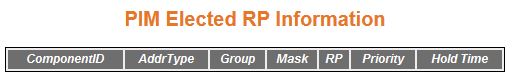
| Screen Objective |
This screen displays the PIM Elected RP Information for IP multicast groups. |
Note: This screen displays
only if PIM module is enabled
globally.
|
| Navigation |
|
| Fields |
- Component ID—enter
a unique number to configure the PIM component. The
PIM component corresponds to each instance of a PIM domain and classifies it as
Sparse or Dense mode. This value ranges from 1 to 255.
- Address Type—specifies the address type
of the PIM interface— IPv4.
- Group—displays the IP multicast group
address for which the information about the candidate RP is displayed.
- Mask—displays the multicast group address
mask.
- RP—displays the RP Address
of the DF Election row.
- Priority—displays the priority of the
interface which will be advertised as a Candidate-RP. The priority value ranges from
0 to 255. The default value is 192.
- Hold Time—displays the time remaining
for the advertisement of a Candidate RP to
be aged out. This value ranges from 0 to 255 seconds. This value is
0 for the local router that is not configured as BSR.
|
PIM DF Information
Figure 12. PIM DF Information
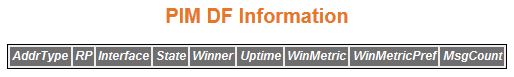
| Screen Objective |
This screen displays the PIM DF (Designated Forwarder) information
for IP multicast groups. |
Note: This screen appears only
if PIM module is enabled globally.
|
| Navigation |
|
| Fields |
- Address Type—specifies
the address type of the PIM interface—
IPv4.
- RP—displays the RP Address
of the DF Election row.
- Interface—displays the index value of
the PIM interface.
- State—displays the election state of
the router for the specified RP address and
interface. The options are offer, win, lose, or back off.
- Winner—displays the address of the DF election winner for the specified RP address and interface.
- Uptime—displays the uptime of the DF election winner for the specified RP address and interface.
- Winner Metric—displays the address of
the DF election winner for the specified
RP address and interface.
- Winner Metric Preference—displays the
metric preference of the DF election
winner for the specified RP to
reach the RP.
- Message Count—displays the number of DF messages sent by the router for
the specified RP and interface.
|