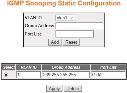
IGMP Snooping

This section describes Internet Group Management Protocol (IGMP) Snooping configuration.

IGMP (Internet Group Management Protocol) is the protocol used by a host for informing a router when it joins (or leaves) an Internet multicast group. IGMP is only used on a local network; a router must use another multicast routing protocol to inform other routers of group membership. IGS (IGMP Snooping) is the process of listening to IGMP network traffic (i.e. the IGMP conversation between hosts and routers). In IGS, a host computer uses IGMP to inform a router that it intends to listen to a specific multicast address. If another computer snoops such packets, the other computer can learn the multicast sessions to which the computers on the local network are listening. IGS significantly reduces traffic from streaming media and other bandwidth-intensive IP multicast applications.

To access IGMP Snooping screens, go to Multicast > IGMP Snooping.

IGMP Snooping Configuration - Basic Settings

By default, the tab IGMP Snooping displays the IGMP Snooping Configuration screen.

Figure 1. IGMP Snooping Configuration


Screen Objective 
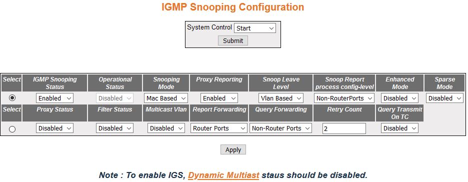
This screen allows the user to configure basic settings such as IGMP snooping status, Operational Status, Snooping Mode, Proxy Reporting, and Snoop Leave level.
Note:

The fields in second row of the form at the bottom can be modified after clicking the select option in the second row.

To configure IGS, GARP (GMRP (Generic Attribute Registration Protocol) Multicast Registration Protocol) must be disabled.
Navigation

Multicast > IGMP Snooping > Basic Settings

Fields
  • Select—select the option button to configure the selected parameters
  • System Control—select the System Control status of IGS in the switch. The default option is Start. The list contains:
    • Start—starts the IGMP snooping and allocates the resources required by the IGS module. During the protocol start-up, it creates semaphore, RBTree, hash table, and also initializes the timer task.
    • Shutdown—all resources are released back to the system and the module stops running. All timers are stopped. The RBTree, hash table, and allocated memory pools are deleted.
  • IGMP Snooping Status—select the global status of IGS in the switch. The default option is Disabled. The list contains:
    • Enabled—starts the IGMP Snooping operations.
    • Disabled—stops performing the IGMP Snooping operations.
  • Operational Status—displays the Operational status of the IGS (I in the switch. The default option is disabled. The list contain:
    • Enabled—indicates that IGS protocol is currently enabled in the system.
    • Disabled—indicates that IGS protocol is currently disabled in the system.
Fields (cont)
  • Snooping Mode—select the IGMP snooping mode. Modes are provided with redundancy support. The default option is MAC-Based. The list contains:
    • IP based—IGS protocol operation is based on the IP address and group address. This mode is chosen if the hardware supports programming of S, G and *, and G entries
    • MAC based—hardware supports only MAC-based multicast tables and the snooping protocol operation is based only on the group address.
  • Proxy Reporting—select the Proxy Reporting status in the switch. IGMP snooping with Proxy Reporting or report suppression actively filters IGMP packets to reduce IGS network traffic. The default option is Enabled. The list contains:
    • Enabled—switch generates reports and forwards them to the router, based on the available host information.
    • Disabled—switch acts as transparent snooping bridge. The switch forwards all v3 reports and a single v2 report to the router.
  • Snoop Leave Level—select the Leave processing mechanism to be implemented at the VLAN level or at port level. When the switch intercepts a leave group message on a switch port, it normally sends a query to that multicast group through the same switch port. If no hosts respond to the query and no multicast routers have been discovered on the switch port, that port is removed from the multicast group. The default option is VLAN Based. The list contains:
    • VLAN Based—configures the leave mechanism at the VLAN level. In VLAN -based leave processing mode, Fast Leave functionality which is configurable per VLAN or normal leave configurations are available for processing Leave messages.
    • Port Based—configures the Leave mechanism at port level. In Port-Based leave processing mode, the explicit host tracking functionality, the fast leave functionality, or normal leave, which are configurable on an interface, can be used for processing the Leave messages.
  • Snoop report Process Config Level—incoming report messages. The default option is Non-RouterPorts. The list contains:
    • Non-RouterPorts—the incoming report messages are processed only in the Non-Router Ports. Report message received in the router ports are not processed.
    • All-Ports—the incoming report messages are processed in all ports including router ports.
Fields (cont)
  • Enhanced Mode—select the operating status of snooping module. The default option is Disabled. The list contains:
    • Enabled—the snooping module operates in Enhanced Mode. This mode enhances the operation of IGMP snooping module to duplicate multicast traffic by learning multicast group entries based on the port and inner VLAN. This mode of operation is applied when the downstream devices are less intelligent or not capable of duplicating Multicast traffic. The module multicasts from an Outer VLAN (SVLAN) to a set of ports & inner VLANs (CVLAN). In this mode, an S-tagged multicast data or a query packet from one port can result in multiple copies of the packet on the same egress port, each with a different C-tag. The Inner VLAN (CVLAN) will typically have a valid value within the designated range.
    • Disabled—this mode of operation is applied when downstream device can perform duplication of Multicast traffic. In this mode, the module multicasts from an Outer VLAN (SVLAN) to a set of ports. The Inner VLAN (CVLAN) will typically have a value of zero. In this mode, an S-tagged multicast data or query packet from one port can result in multiple packets on separate egress ports, with only one packet on per egress port with an S-tag or with no tag.
    Note:

    Enhanced mode is in Enabled state only when the Snooping Mode is set as IP Based.

  • Sparse Mode—select whether the snooping module will operate in the Sparse Mode or Non-Sparse Mode. This option is designed to select whether the unknown multicast traffic should be dropped or flooded when there is no interested listener. The default option is disabled. The list contains:
    • Enabled—the IGS module drops the unknown multicast traffic when there is no listener to the multicast data.
    • Disabled—the IGS module forwards the unknown multicast traffic. The multicast data gets flooded to the member port of VLAN.
    Note:

    Sparse mode is in enabled state, only when the Snooping Mode is set as IP Based.

  • Proxy Status—select the status of the proxy in the system. In proxy mode, all reports and queries generated by the switch will be having the switch IP as the source IP. The list contains:
    • Enabled—enables proxy in the system. The switch acts as a querier for all downstream interfaces and as a host for all upstream interfaces.
    • Disabled—disables proxy in the system.
    Note:

    Proxy status can be enabled only if Proxy-reporting is disabled.

Fields (cont)
  • Filter Status—select the filter status. The default option is Disabled. The list contains:
    • Enabled—enables the IGS filtering feature. The channel registration is restricted from addition to the database if it is to be filtered. In transparent snooping, the filtered packet will not be added to the snooping database but will be forwarded upstream.
    • Disabled—disables the IGS filtering feature. All filter related configurations are allowed but the incoming report will not be subjected to the filter process. IGS module programs the hardware to remove the configured rate limit. It flushes all the registrations learnt through a port if a threshold limit is configured for this interface.
  • Multicast VLAN—select the Multicast VLAN (MVLAN) status. Multicast VLAN (MVLAN) feature can be used for applications where wide-scale deployment of multicast traffic is necessary. MVLAN registration allows a subscriber on a port to subscribe and unsubscribe to a particular multicast stream on any of the multicast VLANs. MVLANs enable efficient multicast data flow in separate MVLANs, while normal data flows through other/different VLANs. The default option is Disabled. The list contains:
    • Enabled—enables the Multicast VLAN feature. Router sends a single copy of the data for the particular MVLAN, instead of forwarding a separate copy of the multicast data to each VLAN. This saves the network bandwidth.
    • Disabled—disables the multicast VLAN feature. With MVLAN disabled, a separate copy of the multicast data has to be forwarded from the router.
  • Report Forwarding—select whether the report must be forwarded to all ports or only to router ports. The port which receives the query message from the router is a router port. The default option is Router Ports. The list contains:
    • Router Ports—forwards reports only to the router ports.
    • All Ports—forwards reports to all ports of the VLAN.
    • Non-edge—forwards the reports to non-edge ports detected by spanning tree protocol.
  • Query Forwarding—select whether the query to be forwarded to the entire member ports of the VLAN or to Non-router Ports. The default option is Non-Router Ports. The list contains:
    • All Ports—the query messages are forwarded to all the member ports of the VLAN.
    • Non-Router Ports—the query messages are forwarded only to the non-router ports.
  • Retry Count—enter the maximum number of group specific queries sent on a port on reception of an IGMPv2 leave message. This value ranges between 1 and 5. The default value is 2.
Fields (cont)
Note: When the switch receives leave message on a port, it sends group specific query to check if there are any other interested receivers for the group. The Retry Count defines the maximum number of queries sent by the switch before deleting the port from the group membership information in the forwarding database. If the maximum retry count exceeds the Retry Count, the port will be deleted from the multicast group membership information in the forwarding database and received leave message will be forwarded onto the router ports if there are no interested receivers for the group.
  • Query Transmit on TC—select path redundancy for IGMP Snooping queries transmission to be enabled or disabled whenever topology changes. The default option is Disabled. The list contains:
    • Enabled—provides path redundancy while preventing undesirable loops in the network. When enabled, it allows the path to exchange information so that only one of them will handle a given message that is being sent between two computers within the network.
    • Disabled—path redundancy is disabled, and it leads to flooding of data.
Buttons
  • Submit—modifies attributes and saves the changes.
  • Apply—modifies attributes for the selected entry and saves the changes.

IGMP Snooping Timer Configuration

Figure 2. IGMP Snooping Timer Configuration


Screen Objective This screen allows the user to set Router Port Purge Interval, Group-Member Port Purge Interval, Report Forward Interval, and Group Query Interval.
Navigation

Multicast > IGMP Snooping > Timer

Fields
  • Router Port Purge Interval (Secs)—enter the time interval after which the learnt router port will be purged. This option is to determine the aliveness of router ports. This value ranges from 60 to 600 seconds. The default value is 125 seconds.
Note:

For each router port learnt, the timer runs for the configured port purge time interval. When the timer expires, the learnt router port entry is purged. If control messages are received from the router before the timer expiry, the timer restarts.

Fields (cont)
  • Group Member Port Purge Interval (Secs)—enter the time interval after which a learnt port entry is purged if IGMP reports are not received on a port. This value ranges from 130 to 1225 seconds. The default value is 260 seconds
    Note:

    For each port on which report has been received, this timer runs for the configured time. This timer will be restarted whenever a report message is received from a host on the specific port. If the timer expires, the learnt port entry will be purged from the multicast group.

  • Report Forward Interval (Secs)—enter the time interval within which the next report messages for the same multicast group will not be forwarded. This timer is used when both proxy and proxy-reporting is disabled. This option is to perform Join Aggregation of IGMP membership report. This value ranges from 1 to 25 seconds. The default value is 5 seconds.
    Note:

    This is the interval (in seconds) within which report messages for the same multicast group will not be forwarded. The Report Forward Interval is per multicast group. This timer is started as soon as a report message for that group is forwarded out. Within this ReportForwardInterval, if another report for the same group arrives, that report will not be forwarded.

  • Group Query Interval (Secs)—enter the interval value for which the snooping switch waits for the membership reports from the interested receivers for the given multicast group after sending out query messages. This value ranges from 2 to 5 seconds. The default value is 2 seconds parameters
Buttons
  • Apply—modifies attributes and saves the changes.
  • Reset—resets to default value and discards all user input.

IGMP Snooping VLAN Configuration

Figure 3. IGMP Snooping VLAN Configuration


Screen Objective This screen allows the user to configure IGMP Snooping on specific VLANs.
Navigation

Multicast > IGMP Snooping > VLAN Configuration

Fields
  • VLAN ID—select the VLAN Identifier that uniquely identifies a specific VLAN from the list already in the system. The IGMP snooping configuration is performed for this specific VLAN ID.
  • IGMP Snooping Status—select the status of IGMP snooping on the specified VLAN. The default option is Disabled. The list contains:
    • Enabled—IGS is enabled on the specified VLAN. A switch will listen for IGMP messages from the host connected on those interfaces and build the software. This ensures that only the ports that require a given multicast stream actually receive it
    • Disabled—IGS is disabled on the specified VLAN.
Fields (cont)
  • Operating Version/ Configured Version—select the Operating Version of IGS for the specified VLAN. The default option is Version 3. The list contains:
    • Version 1—the port list connected to listeners of multicast groups is built based on IGMP membership reports, query, and Leave messages.
    • Version 2—the port list connected to listeners of Multicast groups is built based on IGMP membership reports, query, and Leave messages, with added support for low leave latency; low leave latency is a reduction in the time it takes for a multicast router to learn that there is no longer any member of a particular group present on an attached network.
    • Version 3—the port list is based on source filtering information sent by IGMPv3 hosts in their membership reports to build Source-Specific Multicast (SSM) groups. Support for source filtering is the ability for a system to report interest in receiving packets only from specific source addresses or from other than specific source addresses sent to a particular multicast address.
  • Fast Leave—select the Fast Leave status of IGS. The default option is Disabled. The list contains:
    • Enabled—on receipt of a single Leave message, the port information is immediately removed from the multicast group entry. The switch immediately removes the port from the forwarding table without sending a group specific query. The Fast Leave functionality does not verify if other interested receivers are still present for the multicast group on the same port.
    • Disabled—normal Leave functionality gets enabled. The switch checks if there are any interested receivers for the group by sending a group specific query before removing the port from the forwarding table.
  • Querier Status/ Configured Querier Status—select whether the switch is configured as a querier in a VLAN. The default option is Disabled. The list contains:
    • Enabled—the switch starts acting as a querier and sends query messages until it receives best querier information. The switch sends general queries at regular time intervals. This querier message takes part in querier election.
    • Disabled—the switch is configured as non-querier, does not propagate any general query messages, and does not take part in querier election.
  • Startup Query Count—enter the number of queries to be sent during start-up of querier election process at the interval of start-up query interval. This value ranges from 2 to 5. The default value is 2.
  • Startup Query Interval (secs)—enter the interval (in seconds) between the start-up general query messages sent by the switch (querier) during the start-up of querier election process. This value ranges from 15 to 150 seconds. The default value is 32 seconds.
    Note:

    This value should be less than or equal to one fourth of query interval value configured for the VLAN.

Fields (cont)
  • Querier Interval (secs)—enter the time period between which the general queries are sent by IGMP snooping, when the switch is configured as querier on a VLAN. The switch waits for the configured time period after sending a general query message. On the expiry of this query interval, the switch again sends the general query message and restarts the timer. This value range between 6 and 600 seconds. The default value is 125 seconds.
  • Other Querier Present Interval (secs)—enter the time period (in seconds) that must pass before a multicast router decides that there is no longer another multicast router which should be the querier. This value ranges from 120 to 1215 seconds. The default value is 255 seconds.
    Note:

    This value must be >= ((Robustness Variable * Query Interval) + (Query Response Interval/2)).

    Note:

    The Robustness Variable tunes IGMP to expected losses on a link. IGMPv3 is robust to (Robustness Variable—1) packet losses.

  • Router Port List—enter the static Router Port List for VLAN. When the snooping switch receives a Router advertisement message through a port, the port is identified as router port and is added in the router port list. The default option is None.
  • Blocked Router Port List—enter the list of ports which are configured statically as blocked router ports. For a blocked router port, the software discards queries, PIM (Protocol Independent Multicast) / DVMRP (Distance Vector Multicast Routing Protocol), and Data Messages and prevents the port from ever becoming a router port. The blocked router port feature does not involve any hardware programming. Multicast data is dropped for a blocked router port. Reports are not forwarded to a blocked router port. Reports coming from a blocked router port are not processed. The default option is None.
    Note:

    A port cannot be configured as a blocked router port if it is already configured as static router port.

  • Multicast VLAN Profile—select the multicast profile identification configured for a particular VLAN and used for multicast VLAN classification. When any untagged report or Leave message is received, and the Group & Source address in the received packet matches any rule in this profile, the received packet is classified to be associated with the VLAN to which this profile is mapped.
  • Max Response Code—enter the maximum response code advertised in queries which are sent over this VLAN. This value ranges from 0 to 255 tenths of a second. The default value is 100.
  • Current Version—displays the working IGMP Version on the VLAN.
  • Current Querier Status—displays the current querier status in the VLAN. The value can be enabled or disabled.
Buttons
  • Add—adds and saves new configuration.
  • Reset—resets to default value and discards all user input.
  • Apply—modifies attributes and saves the changes.
  • Delete—deletes the selected entry.

IGMP Snooping Interface Configuration

Figure 4. IGMP Snooping Interface Configuration


Screen Objective This screen allows the user to set Router Port Purge Interval, Group-Member Port Purge Interval, Report Forward Interval and Group Query Interval.
Navigation

Multicast > IGMP Snooping > Interface Configuration

Fields
  • Interface Index—select the interface index of the port from the list of interfaces.
  • Leave Mode—select the mechanism to be used for processing leave messages in the downstream interface. The default option is Normal Leave. The list contains:
    • Explicit Tracking—leave messages are processed using the explicit tracking mechanism. On receipt of the leave message, the switch uses its learnt database to determine whether the specified multicast group has a single receiver or multiple receivers attached to the port. The switch removes the port from the multicast group entry only when no other receivers are present in the same group.
    • Fast Leave—leave messages are processed using the Fast Leave mechanism. On receipt of a single leave message the port is immediately removed from the group entry. The fast leave functionality does not verify if other interested receivers are still present in the multicast group on the same port. Hence the feature can be used effectively only in a point-to-point connection.
    • Normal Leave—a group or group-specific query is sent on the interface when a leave message is received. Once snooping switch sends the leave message for a multicast group, the snooping switch sends out query messages and waits specified time for the membership reports from the interested receivers for the given multicast group.
    Note:

    This field can be configured only when Snoop Leave Level is set to Port Based

Fields (cont)
  • Threshold Limit Type—select the type of limit to be applied for the interface. The threshold limit will be applied when reports are received from the downstream interface. The default option is None. The list contains:
    • None—no limiting is done.
    • Groups—limits the IGMP report message based on the group registration allowed per downstream interface.
    • Channels—limit is applied only for IGMPv3 Include and Allow reports based on the S&G registration that are allowed per downstream interface.
  • Threshold Limit—enter the maximum number of unique entries (channel or group) which can be learned simultaneously on the interface. The software allows the configuration of threshold limit per downstream interface. Downstream interface refers to a physical port in the default mode of operation or to a combination of inner VLAN and physical port in the enhanced mode of operation of the switch. This value ranges from 0 to 4294967295. The default value is 0.
    Note:

    This field can be configured only when the Threshold Limit Type is set.

  • Rate Limit—enter the rate limit for a downstream interface in number of IGMP packets per second. The MDL rate limit per port will eliminate bursts or attacks coming from the specific physical port and exhausting the system resources. This value ranges from 0 to 4294967295 with default value of 4294967295.
  • Filter Profile ID—select the Filter Profile ID. This unique identifier configured by the administrator for a particular Internet address type identifies each of the profile entries. This ID is configured for the downstream interface - default of 0.
Buttons
  • Apply—modifies attributes and saves the changes.
  • Delete—deletes the selected entry.

IGMP Snooping VLAN Router Port Configuration

Figure 5. IGMP Snooping VLAN Router Port Configuration


Screen Objective This screen allows the user to configure the details of the router port.
Navigation

Multicast > IGMP Snooping > Router Port Configuration

Fields
  • VLAN ID—select the VLAN Identifier that uniquely identifies a specific VLAN from a list of already specified in the system. The IGMP snooping configuration is performed for the entered VLAN ID.
  • Router Port List—enter the router port/port list for the VLAN specified in VLAN ID field. When the snooping switch receives a router advertisement message through a port, the port is learnt as router port. These ports are part of this router port list. User can enter the router port/port-list on which he wants to configure the purge interval / version.
  • V1/V2 Router Port Purge Interval—enter the time interval after which the switch assumes that there are no v1/v2 routers present on the upstream port. For each router port learnt, this timer runs for 'RouterPortPurgeInterval' seconds. When the time is over, the learnt router port entry is purged. If control messages are received from the router before the timer expiry, then the timer is restarted. This value ranges from 60 to 600. The default value is 125.
  • Static Router Port Version—select the operating version of the IGMP proxy on the upstream router port. The default option is Version 3. The list contains:
    • Version1—indicates that the operating version of IGMP proxy is version 1
    • Version2—Indicates that the operating version of IGMP proxy is version 2
    • Version3—Indicates that the operating version of IGMP proxy is version 3
  • Router Port—displays the interface index of the port which is defined as an upstream router port. When the snooping switch receives a Router advertisement message through a port, the port is identified as router port.
  • Router Port Configuration Version—displays the configured version of the IGMP Proxy on the upstream router port. The default value is Version 3.
  • Router Port Version—displays the operating version of the IGMP proxy on the upstream router port. The default value is Version 3.
  • Router Port—displays the time interval after which the switch assumes that there are no IGMPv3 routers present on the upstream port. When the timer expires, the learnt router port entry is purged. If control messages are received from the router before the timer expiry, the timer is restarted. This value ranges from 60 to 600. The default value is 125.
    Note:

    For each V3 router port learnt, the timer runs for time interval calculated based on the formula “V3 Router port purge Interval = ((V3 Querier Query Interval * Robustness variable) + Max ResponseTime) seconds.

Buttons
  • Add—adds and saves new configuration.
  • Modify—modifies attributes and saves the changes.
  • Delete—deletes the selected entry.

IGMP Snooping VLAN Router Ports

Figure 6. IGMP Snooping VLAN Router Ports


Screen Objective This screen displays the Router Port List table. All dynamic and static ports are listed in the screen
Navigation

Multicast > IGMP Snooping > Router Ports

Fields
  • VLAN ID—displays the VLAN Identifier that uniquely identifies a specific VLAN on which router ports are learnt / configured.
  • Dynamic Port List—displays the lists of ports on which routers are present.
    Note:

    These router ports are learnt through control messages received from routers but can be configured also statically.

  • Static Port List—displays the list of ports which are configured statically as router ports. Only static router ports will be restored during save restore. The default operating version for static router ports will be IGMPv3, based on the address type.

IGMP Snooping Static Configuration

Figure 7. IGMP Snooping Static Configuration


Screen Objective This screen allows the user to configure the IGMP snooping on static interface.
Navigation

Multicast > IGMP Snooping > Static Entry

Fields
  • VLAN ID—displays the VLAN Identifier that uniquely identifies a specific VLAN on which router ports are learnt / configured.
  • Group Address—enter the Group MAC Multicast address that is learnt.
  • Port List—enter the learnt ports list for which the multicast data packets for the group will be forwarded.
Buttons
  • Add—adds and saves new configuration.
  • Reset—resets to default value for respective fields and discards all user inputs.
  • Apply—modifies attributes and saves the changes.
  • Delete—deletes the selected entry.

MAC Based Multicast Forwarding Table

Figure 8. MAC Based Multicast Forwarding Table


Screen Objective This screen displays the IGMP group information such as MAC-based or IP-based Multicast Forwarding Table. Multicast Forwarding table is populated with a list of ports interested in receiving multicast traffic to avoid flooding of multicast data traffic.
Note:

When snooping is disabled on the port, all entries in the group table and forwarding table are deleted for the port.

Navigation

Multicast > IGMP Snooping > FWD Information

Fields
  • VLAN ID—displays the VLAN Identifier that uniquely identifies a specific VLAN. The MAC based multicast forwarding entry is displayed for the requested VLAN ID.
  • Group Address—displays the Group MAC Multicast address that is learnt.
  • Port List—displays the learnt ports’ list for which the multicast data packets for the group will be forwarded.

Multicast Receiver Table

Figure 9. Multicast Forwarding Table


Screen Objective This screen displays a multicast report sent by each host in a multicast group requesting data from a specific source.
Navigation

Multicast > IGMP Snooping > Mcast Receiver Info

Fields
  • VLAN ID—displays the VLAN Identifier that uniquely identifies a specific VLAN. The MAC-based multicast forwarding entry is displayed for the requested VLAN ID.
  • Group ID—displays the multicast group IP address for which the receiver has sent a request to join the group.
  • Port—displays the port on which the multicast receiver has sent a join request.
  • Host IP—displays the IP address of the multicast receiver that has sent a request to join the multicast group.
  • Source IP—displays the unicast source IP address of the data source that sends multicast data to the group.
  • Filter Mode—displays the mode that has been registered by the multicast receiver for the unicast source IP address specified. The list contains:
    • Include—reception of packets sent to the specified multicast address is requested *only* from those IP source addresses listed in the source-list parameter.
    • Exclude—reception of packets sent to the given multicast address is requested from all IP source addresses *except* those listed in the source-list parameter.