This section describes Internet Group Management Protocol
(IGMP) Proxy configuration.
Note: This web page is visible in WEBUI, but is not
supported for this release.
IGMP Proxy enables
the system to issue IGMP host
messages on behalf of the discovered hosts. IGMP proxy
provides queue interface and socket interface options to receive
and transmit the IGMP control packets
and multicast data packets.
IGMP proxy device performs
router portion of IGMP on the
downstream interfaces and host portion of IGMP on
the upstream interfaces. IGMP proxy
device consolidates the reports received in the downstream interfaces,
and sends a summarized report on to the upstream interface.
To access IGMP Proxy screens, go to .
IGMP Proxy Configuration
By
default, the tab Basic Settings displays
the IGMP Proxy Configuration screen.
Figure 1. IGMP Proxy Configuration

| Screen Objective |
This screen allows the user to configure the IGMP Status. |
| Navigation |
|
| Fields |
- Proxy Status—enables/
Disables IGMP Proxy in the Switch.
The default option is Disabled. The list contains:
- Enabled—starts IGMP proxy module.
- Disabled—stops IGMP proxy
module.
Note: IGMP proxy
can be enabled only when the multicast routing protocol PIM is disabled.
|
| Buttons |
- Apply—modifies
attributes and saves the changes.
- Reset—resets to default value for respective
fields and discards all user input.
|
IGMP Upstream Interface Configuration
Figure 2. IGMP
Upstream Interface Configuration
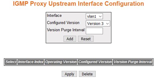
| Screen Objective |
This screen allows the user to configure the IGMP Proxy Upstream Interfaces. |
| Navigation |
|
| Fields |
- Interface—specifies
the Layer 3 VLAN Interface, which
is defined as an upstream interface.
- Interface Index—specifies the index value
of the Layer 3 VLAN Interface,
which is defined as an upstream interface. This is a read-only field.
This value ranges from 1 to 65535.
- Configured Version—specifies the configured
version of the IGMP Proxy device on
the upstream interface. The options are Version 1, Version 2, and
Version 3. Default is Version 3.
- Version Purge Interval—specifies the
interval (in seconds) after which the upstream interface IGMP operating version will be
changed to configured IGMP version.
This value ranges from 60 to 600 seconds.
- Operating
Version—indicates the operating version of the IGMP Proxy device on the upstream
interface. This is a read-only field. The options are Version 1,
Version 2, and Version 3.
|
| Buttons |
- Add—adds and
saves new configuration.
- Reset—resets to default value for respective
fields and discards all user input.
- Apply—modifies attributes and saves the
changes.
- Delete—deletes the selected entry.
|
IGMP Proxy MRoute Configuration
Figure 3. IGMP
Proxy MRoute Configuration

| Screen Objective |
This screen allows the user to view the multicast
routing information for the registered group members. MRoute stands
for multicast static route. |
| Navigation |
|
| Fields |
- Source—indicates
the Unicast Source IP address of the data source that sends multicast
datagrams for the registered multicast groups.
- Group—indicates the IP multicast group
address for which multicast registrations are received.
- Upstream Interface Index—indicates the
index value of the upstream interface on which IP multicast datagrams
are received for the registered group address.
|
IGMP Proxy Next Hop Configuration
Figure 4. IGMP
Proxy Next Hop Configuration

| Screen Objective |
This screen allows the user to view the list
of outgoing interfaces for the multicast forwarding entries. |
| Navigation |
|
| Fields |
- Source—indicates
the Unicast Source IP address of the data source that sends multicast
datagrams for the registered multicast groups.
- Group Adress—indicates the IP multicast
group address for which multicast registrations are received.
- Next Hop Upstream Interface Index—indicates
the index value of the interface on which multicast registrations
for the group are received.
- Next Hop Stateindicates the state of
the outgoing interface on which the multicast registrations have
been received. The options are:
- Forwarding—denotes that
the entry is created.
- Prune— prune messages are used to prevent future messages from
propagating to routers without group membership information (RFC
3973).
|