Used to control the traffic allowed to pass through ports
on the switch.
ACL (Access
Control List) specifies rules that allow or block specific traffic
through the switch. These rules place certain restrictions on the
request types sent from computers to the Internet and vice versa. iS5Com
provides support for ACLs based
on chipsets capability and provides separate configuration parameters
for the same.
To access ACL screen, go to .
MAC ACL Configuration
By default, the tab ACL displays
the MAC ACL Configuration screen.
Figure 1. MAC ACL Configuration—Part A
Figure 2. MAC ACL Configuration—Part B
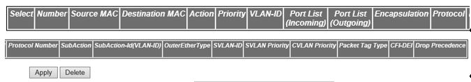
| Screen Objective |
This screen allows the user to create a MAC (Media Access Control) ACL and configure its parameters. |
| Navigation |
|
| Fields |
- ACL Number—enter
the ACL number which is the unique
identifier for the access list. This value ranges from 1 to 65535.
- Source MAC—enter the source unicast MAC address for which the access
control must be applied. The default value is 0 which implies that
any source MAC address can be
filtered
- Destination MAC—enter the destination
unicast MAC address for which
the access control must be applied. The default value is 0, which
implies that any destination MAC address
can be filtered.
Note: The status of the access list can be Active
only if both the source and destination MAC addresses
are configured.
- Action—select the action to be taken
on the packet if the filter rule matches. The default option is
Permit. The list contains:
- Permit—forwards the packet according
to the forwarding rules.
- Deny—discards the packet.
- Redirect—switches the packet according to the redirect rules.
Note: If
the selected Action is Redirect, the Redirect Interface Group screen
needs to be configured.
- Priority—enter priority of the L3 filter
to decide which filter rule is applicable when the packet matches
with more than one filter rules. Higher value of ‘filter priority’
implies a higher priority. This value ranges from 1 to 255. The
default value is 1.
- VLAN ID—select the VLAN ID (Identifier) for which
the access control has to be applied. This value ranges from 0 to
4094. The default value is 0, which implies that this object is
not used.
Note: For provider bridge, the VLAN ID
is treated as customer VLAN ID.
- Port List (Incoming)—enter the incoming
port list which is the set of ports for which the ingress filtering
is applied.
- Port List (Outgoing)—enter the outgoing
port list which is the set of ports for which the egress filtering
is applied.
|
| Fields (cont). |
- Encapsulation—enter
the encapsulation type of the packet for which the access control
has to be applied. This value ranges from 1 to 655351.
- Protocol—select the non-IP Protocol type
of the packet for which the access control has to be applied. The
default value is 0, which means that the filter is applicable for
all protocols. The list contains:
- aarp—specifies Ethertype
AppleTalk Address Resolution Protocol (AARP) that
maps a data-link address to a network address.
- amber—specifies EtherType DEC-Amberdec-spanning—specifies EtherType Digital
Equipment Corporation (DEC) spanning
tree
- decnet_iv—specifies EtherType DECnet
Phase IV protocol
- diagnostic—specifies EtherType DEC-Diagnostic
- dsm—specifies EtherType DEC-DSM/DDP
- etype-6000—specifies EtherType 0x6000
- etype-8042—specifies EtherType 0x8042
- at—specifies EtherType DEC-LAT
- lavc-sca—specifies EtherType DEC-LAVC-SCA
- mop-consol—specifies EtherType DEC-MOP
Remote Console
- mop_dump—specifies EtherType DEC-MOP
Dump
- msdos—specifies EtherType DEC-MSDOS
- mumps—specifies EtherType DEC-MUMPS
- netbios—specifies EtherType DEC—NETwork
Basic Input / Output System (NETBIOS)
- vines-echo—specifies EtherType Virtual Integrated NEtwork Service
(VINES)
- vines-ip—specifies EtherType VINES IP
- xns-id—specifies EtherType Xerox Network Systems (XNS) protocol suite
- other—specifies other protocols.
Note: The
protocol number corresponding to the selected protocol is displayed
in the text box next to the protocol.
Note: he protocol
number can be configured only if the Protocol is selected as other. This
value ranges from 1 to 65535.
- Sub-Action—Id
(VLAN-ID)—enter the unique identifier for the VLAN specific
sub action to be performed on the packet. This value ranges from
0 to 4094. The default value is 0.
Note: If the Sub Action
is selected as Modify CFIDEI, the Sub Action Id is either 0 or 1.
Note: If
the Sub Action is selected as Modify DP, the Sub Action Id ranges
from 0 to 3.
Note: If the Sub Action is selected as Modify
DP, the Sub Action Id ranges from 1 to 7.
Note: This field
cannot be configured if the Action is selected as DenY.
Note: This
field cannot be configured if the Sub Action is selected as None
or Strip-Outer Header.
|
| Fields |
- OuterEtherType—enter
the EtherType value of the outer VLAN tag
of a packet. This value ranges from 1 to 65535. The default value
is 0, which implies the don’t care condition—packet with any EtherType
value is considered.
- SVLAN-ID—enter the SVLAN-ID present in the outer
tag to be filtered. This value ranges from 1 to 4094. The default
value is 0.
- SVLAN Priority—enter the service VLAN priority present in the outer
tag to be filtered. This value ranges from 0 to 7. The default value
is 1.
- CV lan Priority—enter the customer VLAN priority value present in
the outer tag to be filtered. This value ranges from 0 to 7. The
default value is 1.
- Packet Tag Type—elect the packet tag
type for which the access control has to be applied. The list contains
Single-Tag and Double-Tag. The default value is Single-Tag.
- Single-Tag—applies
the configured filter parameters on single VLAN tagged packets
- Double-Tag—applies the configured filter parameters on double VLAN tagged packets.
- CFI/DEI—enter the CFI/DEI bit value in the c-vlan tag
or s-vlan tag of the packet for which the access control has to
be applied This value ranges from 0 to 1.
- Drop Precedence/DEI—select the drop precedence
level for which the access control has to be applied. The default
option is Green. The list contains:
- None—sets the drop precedence
level as None.
- Green—sets the drop precedence level as Green.
- Yellow—sets the drop precedence level as Yellow.
- Red—sets the drop precedence level as Red.
|
| Buttons |
- Apply—modifies
attributes and saves the changes.
- Reset—resets to default value for respective
fields and discards all user inputs.
- Apply—modifies attributes for the selected
entry and saves the changes.
- Delete—deletes the selected entry.
|
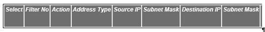
IP Standard ACL Configuration
Figure 3. IP
Standard ACL Configuration
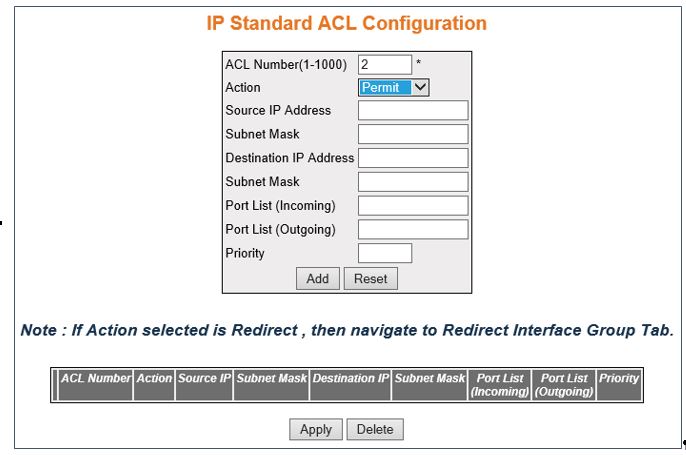
| Screen Objective |
This screen allows the user to set the IP Standard ACL Configuration. Standard ACLs create filters based on IP
address and network mask only (L3 filters only). |
| Navigation |
|
| Fields |
- ACL Number—enter
the standard ACL Number which
is the unique identifier for the standard ACL.
This value ranges from 1 to 1000.
- Action—select the action to be taken
for the access list. The default option is Permit. The list contains:
- Permit—allows the packets when a match has been found
- Deny—drops the packets when a match has been found
- Redirect—switches the packet according to the redirect rules.
Note: If
Action selected is Deny, SubAction, and SubAction-Id(VLAN-ID) fields cannot
be configured.
Note: If Action selected is Redirect, the Redirect
Interface Group screen needs to be configured
|
| Field (cont). |
- Source IP Address—enter
the IP Address matching the packet's source IP address.
- Destination IP Address—enter the destination
IP Address to match against the packet's destination IP address.
Note: The
status of the access list can be Active only if both the source
and destination MAC addresses are configured.
- Subnet
Mask—enter the address mask corresponding to the IP
Address.
- Ports List (Incoming)—enter the incoming
port list which is the set of ports over which the filter is to
be applied for packets ingress at ports in this list.
- Ports List (Outgoing)—enter the out port
list which is the set of ports over which the filter is to be applied
for packets egress at ports in this list.
- Priority—enter priority of the L3 filter
to decide which filter rule is applicable when the packet matches
with more than one filter rules. Higher value of ‘filter priority’
implies a higher priority. This value ranges from 1 to 255. The
default value is 1.
|
| Buttons |
- Apply—modifies
attributes and saves the changes.
- Reset—resets to default value for respective
fields and discards all user inputs.
- Apply—modifies attributes for the selected
entry and saves the changes.
- Delete—deletes the selected entry.
|
IP Extended ACL Configuration
Figure 4. IP
Extended ACL Configuration—Part A
Figure 5. IP Extended ACL Configuration—Part B
Figure 6. IP Extended ACL Configuration—Part C

| Screen Objective |
The screen allows the user to set the IP Extended ACL Configuration. Extended access lists
enable specification of filters based on the type of protocol, range
of TCP /UDP ports
as well as the IP address and network mask (Layer 4 filters). |
| Navigation |
|
| Fields |
- ACL Number—enter
the ACL Number which is the unique
identifier for the Extended access list. This value ranges from
1001 to 65535.
- Action—select the action to be taken
for the access list. The default option is Permit. The list contains:
- Permit—allows the packets when a match has been found
- Deny—drops the packets when a match has been found
- Redirect—switches the packet according to the redirect rules.
Note: If
Action selected is Redirect, the Redirect Interface Group screen
needs to be configured
- Address Type Number—select the type of
IP address used by the entry. The list contains:
- IPV4—sets
the IP address type for the ACL as
IPv4.
- Source IP Address—enter the IP Address
matching the packet's source IP address.
- Subnet Mask—enter the address mask corresponding
to the IP Address.
- Destination IP Address—enter the destination
IP Address to match against the packet's destination IP address.
Note: The
status of the access list can be Active only if both the source
and destination MAC addresses are configured.
- Ports List (Incoming)—enter the incoming
port list which is the set of ports over which the filter is to
be applied for packets ingress at ports in this list.
- Ports List (Outgoing)—enter the out port
list which is the set of ports over which the filter is to be applied
for packets egress at ports in this list.
|
| Field (cont) |
|
| Field(cont). |
- Priority—enter
priority of the L3 filter to decide which filter rule is applicable when
the packet matches with more than one filter rules. Higher value
of ‘filter priority’ implies a higher priority. This value ranges
from 1 to 255 (default of 1).
- DSCP—enter the DSCP (Differentiated
Services Code Point) value to be checked against the packet. This
value ranges from 0 to 63. The default value is 1.
Note: This
field cannot be configured if the protocol is selected as ICMP or OTHER.
- TOS—select the type of service.The default
is None. The list contains:
- None—the ACL does
not match the TOS field in the
packets.
- High Reliability—the ACL matches
the packets with TOS field as
high reliability.
- High Throughput—the ACL matches
the packets with TOS field as
high throughput.
- High Reliability and High Throughput—the ACL matches
the packets with TOS field as high reliability and High throughput.
- Low Delay—the ACL matches
the packets with TOS field as
Low delay.
- Low Delay and High Reliability—the ACL matches
the packets with TOS field as
Low Delay and High Reliability
- Low Delay and High Throughput—the ACL matches
the packets with TOS field as
Low Delay and High Throughput.
- Low Delay, High Throughput and High Reliability—the ACL matches the packets with TOS field as Low Delay, High Throughput,
and High Reliability.
Note: This field cannot be configured
if the protocol other than ICMP is selected.
- Source Port (Min)—enter the TCP /UDP (User
Datagram Protocol) source port from which the access list has to
be applied. This value ranges from 0 to 65535. The default value
is 0.
Note: This field can be configured only if the protocol
is configured as TCP or UDP.
- Source Port (Max)—enter the TCP /UDP source
ports to which the access list has to be applied. This value ranges
from 0 to 65535. The default value is 65535.
Note: This field
can be configured only if the protocol is configured as TCP or UDP.
- Destination Port (Min)—enter the TCP /UDP destination
port from which the access list has to be applied. This value ranges
from 0 to 65535. The default value is 0.
Note: This field cannot
be configured if the protocol is selected as ICMP or OTHER.
- Destination Port (Max)—enter the TCP /UDP destination
port from which the access list has to be applied. This value ranges
from 0 to 65535. The default value is 0.
Note: This field cannot
be configured if the protocol is selected as ICMP or
OTHER.
- Destination Prefix Length—enter the length
of the CIDR (Classless Inter
Domain Routing) prefix carried in the destination IP address. This
value ranges from 0 to 32 for IPv4 addresses
and from 0 to 128 for IPv6 addresses. The default value is 0.
|
| Field(cont). |
- Source Prefix Length—enter
the length of the CIDR prefix
carried in the source IP address. This value ranges from 0 to 32
for IPv4 addresses and from 0
to 128 for IPv6 addresses. The default value is 0.
|
| Buttons |
- Apply—modifies
attributes and saves the changes.
- Reset—resets to default value for respective
fields and discards all user inputs.
- Apply—modifies attributes for the selected
entry and saves the changes.
- Delete—deletes the selected entry.
|