The iMR920 is designed for maximum mounting and display flexibility. It can be equipped with DIN, panel or no mount options.
Prevention of Electrostatic Discharge Damage
The device components are prone to electrostatic discharge (ESD) damage. ESD damage, which can cause intermittent or complete component failures, can occur by voltages as low as 30 V. Potentially destructive static voltages can happen during handling of plastic or foam packing material or when moving components across plastic or carpets.
Some
guidelines to minimize the potential for ESD damage are:

- Always use an ESD wrist strap when you are working with components that are subject to ESD damage, and make sure that ESD wrist strap is in direct contact with your skin.
- If a grounding strap is not available, then to ground yourself, touch the exposed bare metal of the device with the other hand immediately before inserting the component into the device.
- When handling any component that is subject to ESD damage and is to be removed from the device, make sure the equipment end of your ESD wrist strap is attached to the ESD point on the chassis.
- Avoid contact between the component that is subject to ESD damage and clothing. ESD voltages emitted from fabric can damage components.
- When removing or installing a component that is subject to ESD damage, always place its components upside on an antistatic surface, in an antistatic card rack, or in an antistatic bag. If you are returning a component, place it in an antistatic bag before packing it.
Before Installation
- Ensure that you understand how to prevent ESD damage.
- Place the rack in its permanent location, allowing adequate clearance for airflow and maintenance, and secure it to the structure.
- Remove the switch from the shipping package.
- Ensure that you have all necessary parts and tools needed to mount the switch on the rack.

Unpacking Device
- Inspect the package for damage before opening.
- Open the package and visually inspect all items for issues.
- Confirm that all items are available.

General Procedure for Installing and Starting the iMR920
- Review the Compliance Specification for any regulatory requirements.
- Mount the device.
- Connect the failsafe alarm relay.
- Connect power to the device and ground the device.
- Connect the device to the network.
- Configure the device.

Electrical / Mechanical Hazards Prevention
- When installing the device in a closed or multi-device rack, be aware that the operating ambient temperature of the rack may be higher than the ambient temperature of the room. Make sure the rack is installed in a suitable environment that can withstand the maximum ambient temperature generated by the rack.
- Do not exceed the maximum number of devices or weight restrictions specified by the rack manufacturer.
- Do not overload the supply circuit. Refer to the overcurrent protection and power supply ratings specified by the rack manufacturer.
- Make sure the rack and all devices have a proper ground-to-Earth connection. Pay particular attention to power supply connections other than direct connections to the branch circuit (e.g. power strips). Ensure that the rack mount adapters are installed on the correct side of the chassis.
Humidity and Dust Hazards
Do not store the switch in locations where it will be subject excessive dirt and dust and high humidity. Conformal coating is recommended for humid / moist applications.
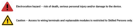
Mounting Raptor on a DIN Rail
Install DIN mount kit on the rear of the iMR920.
Figure 1. Exploded view of DIN mount kit
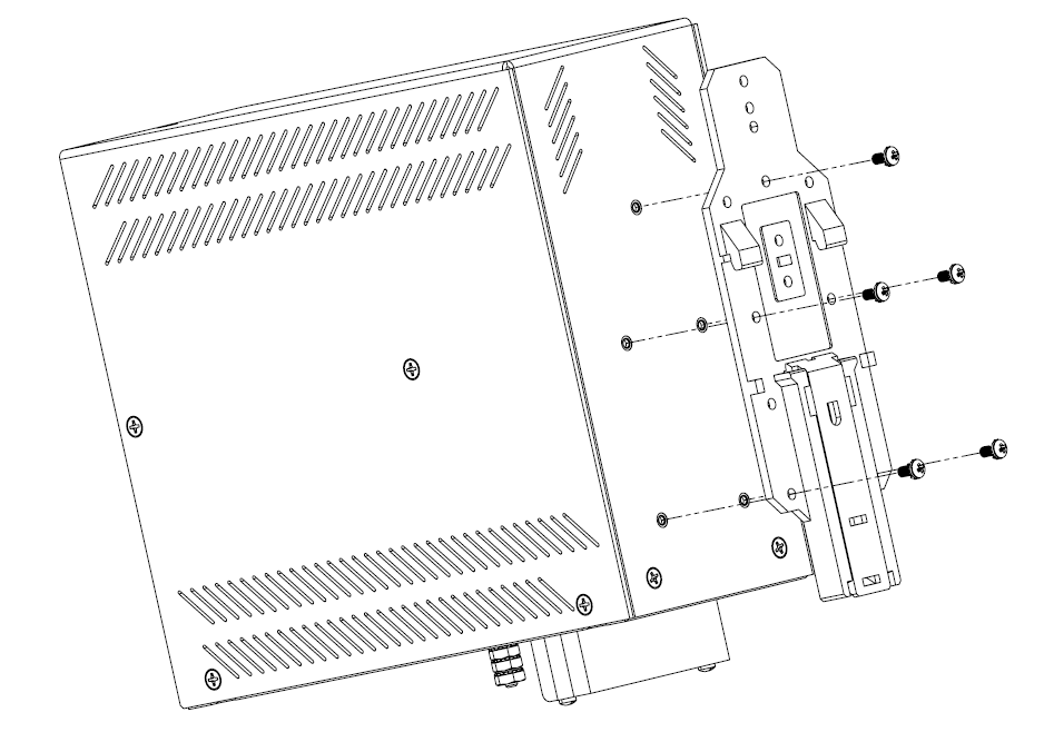
Figure 2. DIN
mount kit mounted on the rear of the iMR920
To secure the device to a standard DIN rail,
perform the following:
- Securely install the DIN rail.
- Place the iMR920 on the rail, then tilt the iMR920 to hook the DIN mount rail tabs over the top edge of the DIN rail.
- Use a flat head screw driver to pull down the locking clip, and then push the iMR920 down and in, the locking clip can then snap over the bottom edge of the DIN rail.
- The iMR920 will now be secured to the DIN rail.
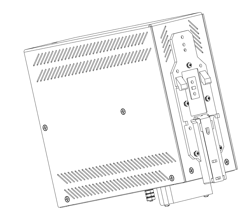
Mounting iMR920 in a Panel
Figure 3. Exploded view of Panel Mount

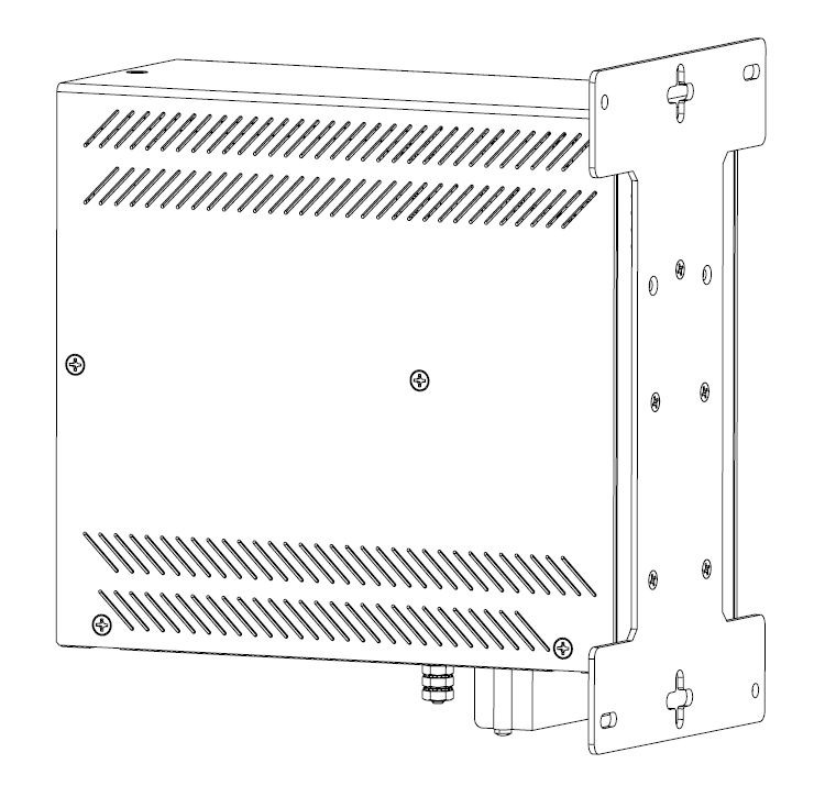
Figure 4. Assembled view of Panel Mount
Equipment Needed for iMR920 Panel Installation
| PART # | QTY | DESCRIPTION |
|---|---|---|
| 1 | 5 (included) | Mounting screw M3 x 0.5, 8mm Length |
| 2 | 1 (included) | Mounting bracket, suitable for maximum M4 screws, or equivalent, to panel |
| 3 | 1 (not included) | Phillips Screwdriver |