Used to configure clock features such as PTP and Clock IWF.
CLOCK link provides the following
links to configure the various clock features of the switch:
- PTP link
allows the user to configure PTP IEEE
1588 Precision Time Protocol and some of its optional features—Acceptable
Master and Alternate Timescale.
- Clock IWF link allows the user to configure
various Clock Interworking parameters such as time source, accuracy,
variance, etc.
PTP
PTP (Precision Time
Protocol) is defined in IEEE 1588 as Precision Clock Synchronization
for Networked Measurements and Control Systems and was developed
to synchronize the clocks in packet-based networks that include
distributed device clocks of varying precision and stability standalone
software which implements IEEE 1588. PTP is
message based protocol which specifies how the real-time clocks
in a distributed system synchronize with each other. PTP creates master-slave hierarchy
to synchronize the clocks in the system.
To access PTP screens,
go to .
PTP Global Configurations
By
default, the tab PTP displays the PTP
Global Configurations screen.
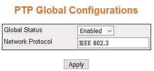
Figure 1. PTP Global Configurations
| Screen Objective |
This screen allows configuring the basic settings
of PTP such as starting the PTP module and creating the primary
context. |
| Navigation |
|
| Fields |
- Global Status—specifies
the system control status of the PTP module.
The default option is Disabled. The list contains:
- Disabled—shuts PTP in a device. This will remove
all PTP related configurations
from the system.
- Enabled—starts PTP in a device.
This will allow the user to configure the PTP parameters.
Note: PTP
module should be started for configuring the PTP parameters.
- Network Protocol—IEEE 802.3.
|
| Buttons |
- Apply—adds and
saves new configuration.
|
Clock Configuration Page
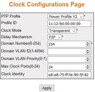
Figure 2. Clock Configuration
Page
| Screen Objective |
This screen allows the user to configure the
clock data set table information. The clock data set table contains
information of the clock on a particular domain. The entries in this
table are created with the default values. |
| Navigation |
|
| Fields |
- PTP Profile—specifies
the type of PTP Profile. The default
profile is Power Profile V2. The options are:
- No Profile
- Default E2E
- Default P2P
- Utility Profile
- Power Profile V2
- Profile ID—1c:12:9d:00:00:00
- Clock Mode—specifies the operating mode
of the clock in the domain. The default option is Transparent. The
list contains:
- Delay Mechanism—specifies the delay mechanism
of the clock in the domain. The default option is P2P. The list
contains:
- P2P—the clock
is in peer-to-peer (P2P) mode.
It measures the time taken for a PTP event
message to transit the device. This information will be updated in
the correction field of the PTP messages.
- E2E— the clock is in end-to-end
(E2E) transparent mode. The clock
calculates the residence time of PTP messages
and measures the link delay of the ingress port of PTP.
- Domain Number (0-254)—specifies the unique
identifier of the domain. This domain ID defines the scope of the PTP message communication, state,
operations, data sets and timescale. this value ranges from 0 to
254.
- Domain VLAN ID (1-4094)—Specifies which
VLAN that the transparent clock messages will use.
- Domain VLAN Priority (0-7)—specifies
the priority of the transparent clock messages.
- Max Clock Ports (0-24)—specifies the
number of the PTP ports. The maximum
and default is 24.
- Clock Identity—displays the unique ID
of the local clock associated with the domain which is e8:e8:75:ff:fe:90:2e:02
|
| Buttons |
- Apply—adds and
saves new configuration.
|
PTP Interfaces
Figure 3. PTP Interfaces

| Screen Objective |
This screen allows the user to add a PTP interface and configure the
port table settings. The port settings table contains PTP configuration information for
a particular port. Valid interface number and type have to be provided
for configuring the port specific parameters. |
| Navigation |
|
| Fields |
- Port—the value
for the context name is default. It cannot be changed.
- Status—select the operational status
of the port in PTP. The default
option is Disabled. Options are:
- Disabled—disables PTP over the interface.
- Enabled—enables PTP over the
interface.
- Min PDelay Interval (sec)—specifies the
delay interval.
- Propagation Delay (nsec)—an estimate
of the current one-way propagation delay in scaled nanoseconds on
the link attached to the port, calculated using the peer delay mechanism.
If the PTP port delay mechanism
is end-to-end, this value will be 0.
|
| Buttons |
- Apply—adds and
saves new configuration.
|
Clock IWF
The Clock IWF module
acts as a layer between the system clock and the protocol which
synchronizes the system clock. This module selects the time source
to set the system clock and maintains the information about the
clock quality such as clock accuracy, class, variance, etc.
Clock Interworking Settings
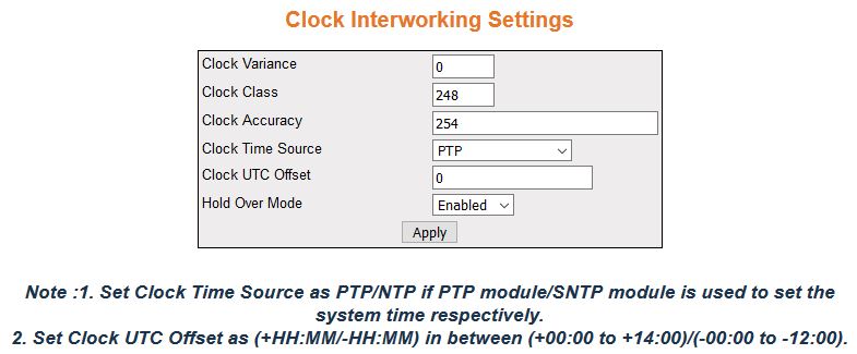
Figure 4. Clock Interworking Settings
| Screen Objective |
This screen allows the user to configure the
clock IWF parameters. |
| Navigation |
|
| Fields |
- Clock Variance—enter
the variance of the primary clock. This object reflects the value
provisioned by the external source (NTP/SNTP/GPS)
that synchronizes the system clock. This value ranges from 0 to
255.The default value is 0 (minimum variance).
- Clock Class—enter the class of the primary
clock. This object reflects the value provisioned by the external
source (NTP/SNTP/GPS)
that synchronizes the system clock. This value ranges from 0 to
255. The default value is 248.
- Clock Accuracy—enter the accuracy of
the primary clock. Clock accuracy is the mean of the time or frequency
error between the clock under test and a perfect reference clock,
over an ensemble of measurements. This object reflects the value provisioned
by the external source (NTP/SNTP/GPS)
that synchronizes the system clock. This value ranges from 32 to
254. The default value is 254.
- Clock Time Source—select the time source
of the primary clock. The system clock is synchronized only through
the specified source. The default option is PTP.
The options are:
- None—does not synchronize the system clock.
- Atomic Clock—synchronizes the system clock through atomic clock.
- GPS—synchronizes the system clock through Global Positioning
System (GPS).
- PTP—synchronizes the system clock through Precision Time Protocol
(PTP).
- NTP—synchronizes the system clock through Network Time Protocol
(NTP).
- Internal Oscillator-Synchronizes the system clock through Internal
Oscillator.
- Clock UTC Offset—enter the current UTC (Coordinated Universal Time)
offset in scaled nanoseconds with respect to the system time. This
value must be in the form of (+HAMM or –HH:MM) and in the range
from +00:00 to +14:00 or—00:00 to—12:00. The default value is 0.
- Hold Over Mode—select the option to specify
whether the system clock is in Hold Over Mode. The default option
is Enabled. The options are:
- Enabled—enables the clock to
be in holdover mode.
- Disabled—disables the holdover mode.
Note: The
clock is said to be in Hold Over Mode if it has been previously
synchronized or synchronized to another clock but is now free-running
based on its own internal oscillator whose frequency is adjusted
using data acquired while it had been synchronized or synchronized
to the other clock.
|
| Buttons |
- Apply—adds and
saves new configuration.
|