This section describes how to configure Multiple Spanning
Tree Protocol (MSTP) on the switch.
MSTP (Multiple Spanning
Tree Protocol) is used to configure spanning tree on per VLAN basis or multiple VLANs per spanning tree. It allows
the user to build several MST over VLAN trunks and a group or associate VLANs to spanning tree instances,
so the topology of one instance is independent of the other instance.
It provides multiple forwarding paths for data traffic and enables
load balancing. It improves the overall network fault tolerance,
as failure in one instance does not affect the other instances.
The
MSTP provides an optional
capability for:
- High availability
- Executing multiple instances of the protocol
- Provider bridging
To access MSTP screens, go to .
Global Information
By default, the tab Basic
Settings displays the Global Configuration screen.
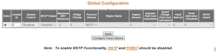
Figure 1. Global Information
| Screen Objective |
This screen allows the user to configure for
each available virtual context the MST module
parameters that are used globally in the switch for all ports. |
Note: To enable MSTP, RSTP and PVRSTP should be disabled in
the selected context.
|
| Navigation |
|
| Fields |
- Select—click
to select the context for which the configuration needs to be done.
- Context Id—displays the virtual context
ID that uniquely represents a virtual switch created in the physical
switch. This value ranges from 0 to 65535. The default value is
0.
- System Control—select the administrative
shutdown status requested by management for the MSTP module. The default option
is Start for the default context and shutdown for the other contexts.
The list contains:
- Start—specifies that MSTP is active in the device on
all ports.
- Shutdown—specifies that MSTP is
shutdown in the device on all ports, and all allocated memory is
release
Note: The administrative status can be set as
Shutdown, only if the MSTP Status
is set as Disabled. The status can be set as Start, only if the RSTP System Control and PVRST System
Control are set as Shutdown using the Layer 2 Management > RSTP >
Global Configuration and Layer 2 Management > PVRST > Global Configuration screen
respectively. MSTP System Control
cannot be shutdown if MSTP status
is enabled.
- MSTP Status—select the administrative
status requested by management for the MST feature. MSTP is used to configure spanning
tree on per VLAN basis or multiple VLANs per spanning tree. It provides
multiple forwarding paths for data traffic and enables load balancing.
The default option is Enabled for the default context and Disabled
for the other contexts. The list contains:
- Enabled—enables MST in the device on all ports.
- Disabled—disables MST in the
device on all ports
Note: To enable MSTP globally in the switch, the MSTP System Control status should
be set as Start. All fields in this screen (except System Control)
are greyed out and cannot be configured, once the MSTP status is set as Disabled.
- Maximum MST Instances—enter the maximum
number of spanning trees to be allowed in the switch. This value
represents the maximum number of active MSTIs (MST Instances) that can be created.
This allows the user to limit the number of spanning tree instances
to be allowed in the switch. This does not count the special MSTID such as PTETID (Provider Backbone
Bridging—Traffic Engineering Multiple Spanning Tree ID), which is
used to identify VIDs used by Ethernet switched paths (ESPs). This
value ranges from 1 to 64. The default value is 64.
Note: The
maximum available number of instances is 16 (values from 0–15 where 0
being CIST).
- Bridge Priority—enter the priority value
that is assigned to the switch. This value is used during the election
of CIST root, CIST regional root and, IST root. This value ranges from
0 to 61440. The default value is 32768. The values set for Bridge Priority
must be in steps of 4096.
|
| Fields (cont) |
- Protocol Version—select
the version of STP in which the
switch is currently running. This allows the user to set the type
of STP to be used by the switch
to form loop-free topology. The default option is MSTP. The list contains:
- STP—sets
the version as STP specified in
IEEE 802.1D.
- RSTP—sets the version as RSTP as
specified in IEEE 802.1w.
- MSTP—sets the version as MSTP as
specified in IEEE 802.1s.
Note: The Fields Region Name
and Region Version are greyed out and cannot be configured, if the
protocol version is set as STP or RSTP.
- Region Name—enter the name for the region’s
configuration to identify the specific MST region.
Each MST region contains multiple
spanning tree instances and runs special instance of spanning tree
known as IST for disseminating
of STP topology information for
other STP instances. The default
value is same as that of the Switch Base MAC Address
configured in the Factory Default Settings screen. This value is
an octet string of maximum size 32.
Note: This field can be configured
only if the protocol version is selected as MSTP.
- Region Version—enter the version that
represents the specific MST region.
The default value is 0. This value ranges from 0 to 65535.
Note: This
field can be configured only if the protocol version is selected
as MSTP.
- Dynamic Path Cost Calculation—select
whether the dynamic path cost calculation is allowed or not. The
path cost represents the distance between the root port and designated
port. The path cost is based on a guideline established as part of
802.1d. The path cost is dynamically calculated using port speed,
when the operational status of the port changes from down to up
or link speed at the time of port creation. The default option is
False. The list contains:
- True—dynamically calculates path
cost based on the speed of the ports whose Admin State is set as
Up at that time. The path cost is not changed based on the operational
status of the ports, once calculated.
- False—dynamically calculates path cost based on the link speed
at the time of port creation
Note: The manually assigned
path cost is used irrespective of the status (True or False) of
the dynamic path cost calculation.
- Speed Change Path Cost Calculation—select
whether the speed change path cost calculation is allowed or not.
The speed change path cost is to be calculated for ports whose speed
changes dynamically. This feature is mainly used for Link Aggregation
ports whose speed changes due to the addition and deletion of ports from
the port channel. The default option is False. The list contains:
- True—specifies that path cost is dynamically calculated for
ports based on their speed at that time. It is calculated if the
speed of the port changes.
- False—specifies that path cost is not dynamically calculated
for ports based on their speed at that time.
Note: The
manually assigned path cost is used irrespective of the status (True
or False) of the path cost calculation if Path Cost for the port
is manually assigned.
|
| Fields (cont) |
- Flush Interval—enter
the value that controls the number of flush indications invoked
from spanning-tree module per instance basis. This value ranges
from 0 to 500 centi-seconds. The default value is 0.
Note: If the
flush interval timer is set to zero, port and instance based flushing occurs
(default functionality). If it is set to non-zero, instance based
flushing occurs (dependent on the flush-indication-threshold value).
- Flush Indication Threshold—enter the
number of flush indications to go before the flush-interval timer
method triggers. This value ranges from 0 to 65535. The default
value is 0.
Note: The flush indication threshold value can be configured
only when flush interval value is other than default value. When
flush indication threshold is default value and flush interval is
non-default value, instance based flushing occurs during the first
flush indication trigger. When the flush indication threshold value
is non-default(x) and flush-interval value is non-default, port
& instance based flushing is triggered until the threshold(x)
is reached. Once the threshold is reached, instance based flushing
is triggered & timer starts.
- BPDU Guard—select the administrative
status for the BPDU guard feature
in the port. This feature configures BPDU guard
globally in MSTP. This global BPDU is applicable if and only
no port specific BPDU Guard is
configured. The default option is Disable. The list contains:
- Enabled—enables BPDU Guard feature on edge ports
globally and moves the port to disabled discarding state when BPDU is received on the edge ports
- Disabled—disables BPDU Guard
feature on edge ports globally.
|
| Buttons |
- Apply—modifies
attributes and saves the changes.
- Configure Trace Options—click to access
the MSTP Traces screen.
|
MSTP Traces
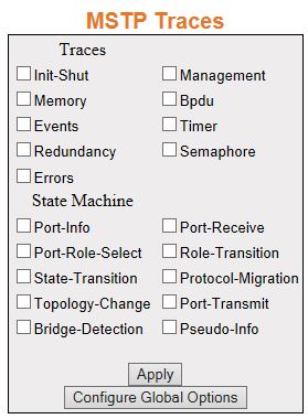
Figure 2. MSTP Traces
| Screen Objective |
This screen allows the user to clear the GARP
statistics for a specified interface or all interfaces |
| Navigation |
screen.
Click Configure
Trace Options.
|
| Fields |
- Traces—select
the traces for which debug statements is to be generated. The options
are:
- Init-Shut—generates debug statements for init and shutdown
traces. This trace is generated on failed and successful initialization
and shutting down of STP related
module and memory.
- Management—generates debug statements for management traces.
- Memory—generates debug statements for memory related traces.
This trace is generated on failed and successful allocation of memory
for STP process.
- BPDU—generates debug statements for BPDU related
traces. This trace is generated on failed and successful reception,
transmission and processing of BPDUs.
- Events—generates debug statements for event handling traces.
This trace is generated to denote events that are posted to STP configuration queue whenever
you configure any of the STP features.
|
| Fields (cont) |
- Traces—the options
are (cont):
- Timer—generates debug statements for timer module
traces. This trace is generated on failed and successful start,
stop and restart of STP timers.
The different STP timers are:
- Forward
delay timer
- Hello timer
- Migration delay timer
- Recent backup while timer
- Received information while timer
- Recent root while timer
- Topology change timer
- Hold timer
- Edge delay timer
- Rapid age duration timer
- Pseudo information hello timer
- Redundancy—generates debug statements for redundancy code flow traces.
This trace is generated in standby node STP while
taking backup of configuration information from active node.
- Semaphore—generates debug statements for state machine variable changes
traces. This trace is generated on failed and successful creation
and deletion of semaphore.
- Errors—generates debug statements for all failure traces of
the traces.
- State Machine—select the SEMs (State Event Machines) for
which debug statements are to be generated to denote the event and
state of the selected SEM. The options
are:
- Port-Info—generates debug statements for port information SEM.
- Port-Receive—generates debug statements for port receive SEM.
- Port-Role-Select—generates debug statements for role selection SEM.
- Role-Transition—generates debug statements for role transition SEM.
- State-Transition—generates debug statements for state transition SEM.
- Protocol-Migration—generates debug statements for protocol migration SEM.
- Topology-Change—generates debug statements for topology change SEM.
- Port-Transmit—generates debug statements for port transmit SEM.
- Bridge-Detection—generates debug statements for bridge detection SEM.
- Pseudo-Info—generates debug statements for port receive pseudo
information SEM.
|
| Buttons |
- Apply—modifies
attributes and saves the changes.
- Configure Global Options—accesses Global
Configuration screen
|
MSTP Timers
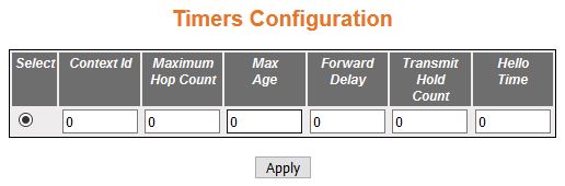
Figure 3. MSTP Timers Configuration
| Screen Objective |
This screen allows the user to configure the
timers used in MSTP protocol
for controlling the transmission of BPDUs during the computation
of loop free topology. This configuration is applied globally in
the switch on all ports. |
Note: This screen displays
the default configuration details only for the context for which
the MSTP System Control status
is set as Start. For the contexts for which MSTP is
shutdown, it displays the value as 0 for all fields.
|
| Navigation |
|
| Fields |
- Select—click
to select the context for which the configuration needs to be applied.
- Context Id—displays the context ID.
- Maximum Hop Count—enter the maximum hop
count value that represents the maximum number of switches that
a packet can cross before it is dropped. This value is used by the
switch to avoid infinite looping of the packets, if it is selected as
the root switch in the topology. This value ranges from 6 to 40.
The default value is 20. The root switch always transmits a BPDU with the maximum hop count value.
The receiving switch decrements the value by one and propagates
the BPDU with modified hop count
value. The BPDU is discarded
and the information held is aged out, when the count reaches 0.
- Max Age—enter the amount of time a port
waits for STP/RSTP information. This value is
used by MSTP while interacting
with STP/RSTP domains
on the boundary ports. This value ranges from 6 to 40 seconds. The
default value is 20.
Note: The maximum age should be lesser than
or equal to 2*(Forward Delay—1.0) and should be greater than or
equal to 2* (HelloTime + 1.0).
- Forward Delay—enter the number of seconds
a port waits before changing from the learning/listening state to
the forwarding state. This value ranges from 4 to 30 seconds. The
default value is 15.
- Transmit Hold Count—enter the value used
by the port transmit state machine for limiting the maximum transmission
rate i.e. the number of packets that can be sent for a given interval.
This value is configured to avoid flooding. Port transmit state
machines use this value to limit the maximum transmission rate.
This value ranges from 1 to 10. The default value is 6.
|
| Fields (cont) |
- Hello Time—enter
the amount of time between the transmission of configuration bridge
PDUs by this node. This value can be either 1 or 2 seconds. The
default value is 2.
|
| Buttons |
- Apply—modifies
attributes and saves the changes.
|
Port Configuration - CIST Settings
Figure 4. CIST
Settings

| Screen Objective |
This screen allows the user to configure the
timers used in MSTP protocol
for controlling the transmission of BPDUs during the computation
of loop free topology. This configuration is applied globally in
the switch on all ports. |
| Navigation |
|
| Fields |
- Select—click
to select the port for which the configuration needs to be applied.
- Port Id—displays the port, which is a
combination of interface type and interface ID. The interface ID
is a combination of a slot number and a port number (slot number/port
number).
- Path Cost—enter the value that contributes
to the path cost of paths towards the CIST Root
which includes this port. The paths’ path cost is used during calculation of
shortest path to reach the CIST root.
The path cost represents the distance between the root port and
designated port. This value ranges from 1 to 200000000. The default
value is 200000 for all physical ports and 199999 for port channels.
Note: The
default value is used as path cost if this field is not configured
and the Dynamic Path Cost Calculation and Speed Change Path Cost
Calculation are set as False. The dynamically calculated path cost
is used if the path cost is not manually configured and one of these
Fields is set as True.The configured value is used as the path cost
irrespective of the status (True or False) of the Dynamic Path Cost Calculation
and Speed Change Path Cost Calculation.
- Priority—enter the priority value that
is assigned to the port. This value is used during the role selection
process. The four most significant bits of the Port Identifier of
the Spanning Tree instance can be modified by setting the CIST Port Priority value. The values
that are set for Port Priority must be in steps of 16. The Priority value
ranges from 0 to 240. The default value is 128.
|
| Fields (cont) |
- Point-to-Point Status—select
the point-to-point status of the LAN segment attached to the port.
The default option is Auto. The list contains.
- ForceTrue—specifies
that port is connected to a point-to-point link.
- ForceFalse—specifies that port is having a shared media connection.
- Auto—specifies that the ports as having a shared media connection,
or a point-point link based on the prevailing conditions.
Note: Port
is considered to have a point-to-point link if: - It is an
aggregator and all of its members can be aggregated.
- The MAC> entity is configured
for full Duplex operation, either manually or through auto negotiation
process (that is, negotiation Mode is set as Auto).
- Edge Port—select the administrative value
of the Edge Port parameter. The default option is False. The list
contains:
- True—sets the port as an edge port (then Port State
is immediately set as forwarding). It is connected directly to a
single end station. It allows MSTP to converge
faster and does not wait to receive BPDUs.
- False—sets the port as a non-Edge port (the spanning tree process
is performed using the MSTP).
It is connected to a routing device such as a switch.
- MSTP Status—select the MSTP status of the port for all
spanning tree instances. This value will override the port’s status
in the MSTI contexts. The default option is Enable. The list contains:
- Enable—enables MST in the
port. MAC frames are forwarded,
and their source addresses are learnt.
- Disable—disables MST in the
ports. MAC frames are not forwarded,
and their source addresses are not learnt.
- Protocol Migration—select the protocol
migration state of the port. This is used to control the protocol
migration mechanism that enables the module to interoperate with
legacy 802.1D switches. The default option is False. The list contains:
- True—specifies that the port transmits BPDUs
based on the spanning tree protocol supported by the receiving switch.
The port is forced to transmit MSTP BPDUs
without instance information.
- False—specifies that the port does not perform protocol migration
mechanism. The port always transmits the standard MSTP BPDUs.
Note: The
protocol migration is greyed out and cannot be configured, if the MSTP Status is set as Disable.
- Hello Time—enter the amount of time between
the transmission of Configuration bridge PDUs by this node in units
of hundredths of a second. This value can be either 1 or 2 seconds.
The default value is 2.
|
| Fields (cont) |
- Auto Edge Status—select
whether the Edge Port parameter of the port is detected automatically
or configured manually. The default option is True. The list contains:
- True—specifies that detection of port as Edge Port happens automatically.
- The port is set as edge port if no BPDU is
received on the port.
- The port is set as non-edge port, if any BPDU is
received by that port.
Note: This overrides the value
set in the field Edge Port, based on the reception of BPDU.
- False—specifies that the auto edge feature is disabled and the
manually configured value for the Edge Port parameter is used.
- Restricted Role—select whether the selection
of port Role as root can be blocked during the role Selection process.
This feature allows the user to block switches external to a core
region of the network from influencing the spanning tree active topology.
The default option is False. The list contains:
- True—blocks
the port from being selected as root port for the CIST or any MSTI, even if it has
the best spanning tree priority vector. It is selected as an alternate
port after the root port is selected.
Note: The blocking of port
from being selected as a root port may cause lack of spanning tree
connectivity.
- False—includes all available ports of the topology, in the root
selection process to select the root for CIST or
any MSTI.
- Restricted TCN—select the status of transmission
of the received topology change notifications and topology changes
to the other ports in the network. This feature allows the user
to block switches external to a core region of the network from causing
address flushing in the region. The default option is False. The
list contains:
- True—blocks the port from propagating the
received topology change notifications and topology changes to other
ports.
Note: The blocking of port may cause temporary loss of
connectivity after changes in a spanning tree active topology as
a result of persistent incorrectly learnt station location information.
- False—allows the port to propagate the received topology change
notifications and topology changes to other ports.
- BPDU Receive—select the processing status
of the received MSTP BPDUs. The default option is True.
The list contains:
- True—normally processes the MSTP BPDUs
received on the port.
- False—discards the MSTP BPDUs received on the port.
- BPDU Transmit—select the BPDU transmission status of the
port. The default option is True. The list contains:
- True—specifies
that MSTP BPDUs
are transmitted from the port.
- False—specifies that MSTP BPDUs transmission is blocked from
the port
|
| Fields (cont) |
Note: This field should be set as False for
ports to be configured as Layer-2 Gateway Port.
- Layer
2-Gateway Port—select whether the port acts as a normal
port or as a L2GP The default
option is False. The list contains:
- True—specifies that the
port operates as a Layer 2 Gateway Port.
- False—specifies that the port operates as a normal port.
Note: BPDU Transmit, Restricted Role
and Restricted TCN should be set
as False before configuring the port as a Layer 2 gateway port (L2GP). L2GP should not be enabled
on ports whose Bridge Port Type is set as PIP (Provider
Instance Port)s or CBP (Customer Backbone
Port)s, as the effect is unknown. L2GP operates
similarly to that of the normal port operation but pretends to continuously
receive BPDUs when Admin State
is set as Up. L2GP cannot be
enabled on ports with Switch Instance Shared Port (SISP) enabled interfaces. The Port
State of the L2GP is always set
as Discarding.
- Loop Guard—select
the status of loop guard. The Loop Guard does age out the information
even if the peer does not send information. If the port continues
to receive information through BPDUs,
the operation on this port will be normal. This is useful when the
neighbor bridge is faulty; that is, the bridge cannot send BPDUs but
continues to send data traffic. The default option is False. The
list contains:
- True—enables the loop guard in the port.
- False—disables the loop guard in the port.
- Root Guard—select the administrative
status for the root guard feature in the port. When enabled, this
feature causes the port not to be selected as Root Port for the CIST or any MSTI, even if it has
the best spanning tree priority vector. Such a Port will be selected
as an Alternate Port after the Root Port has been selected. The
default option is Disabled, and this can cause lack of spanning
tree connectivity. It is set by a network administrator to prevent
bridges external to a core region of the network influencing the
spanning tree active topology; possibly because those bridges are
not under the full control of the administrator.
- Enabled—enables
root guard feature in the port.
- Disabled—disables root guard feature in the port.
- BPDU Guard—the administrative status
for the BPDU guard feature in
the port. This feature configures BPDU guard
globally in MSTP and this global
BPDU is applicable if and only if no port specific BPDU Guard is configured. The default
option is Disable. The list contains:
- Enabled—enables BPDU Guard feature on edge ports
globally and moves the port to disable discarding state when BPDU is received on the edge ports
- Disabled—disables BPDU Guard
feature on edge ports globally.
- Error Recovery—enter the amount of time
to bring the interface out of the error-disabled (err-disabled)
state. This value ranges from 30 to 65535 seconds. The default value
is 30.
|
| Buttons |
- Apply—modifies
attributes and saves the changes.
|
VLAN Mapping
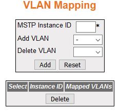
Figure 5. LAN Mapping
| Screen Objective |
This screen allows the user to map / unmap
VLANs for each instance of MSTP and
to create / delete instance specific information for the member
ports of the VLAN. The instance
specific information for the port in one instance is independent
of its information in another instance. |
| Navigation |
|
| Fields |
- Select—select
the instance Id for which the mapping is to be deleted.
- MSTP Instance ID—enter an integer value
that is used to uniquely identify an instance of the MSTP. This value ranges from 1
to 64. The special value 4094 is used in a switch that supports
PBB-TE. This special value represents PTETID that identifies VID
used by Ethernet switched paths (ESPs).
Note: The MSTP Instance ID depends on the
Maximum MSTP instance configured in
the Global Configuration page. Any external agent can separately
provide ESPs. The ESPs do not use spanning tree.
- Add VLAN—select the VLAN that should be mapped to the MSTP instance. The list contains VLAN Name of all VLANs available in the switch.
The mapping of VLAN to the MSTP instance is not done again
if the VLAN is already mapped
to that instance.
- Delete VLAN—select the VLAN that should be unmapped from
the MSTP instance. The list contains VLAN Name for the VLANs available
in the switch. The unmapping of VLAN from
the MSTP instance cannot done
if the VLAN is already unmapped from
that instance.
- Mapped VLANs—displays the VLAN ID mapped to the spanning
tree instance specified. All Instance Specific information for the
member ports of the VLAN will be
created.
|
| Buttons |
- Add—adds and
saves new configuration
- Reset—resets to default value for respective
fields and discards all user inputs
- Deleted—deletes the selected entry
|
Port Settings
Figure 6. Port Settings

| Screen Objective |
This screen allows the user to map / unmap VLANs for each instance of MSTP and to create / delete instance
specific information for the member ports of the VLAN. The instance specific information
for the port in one instance is independent of its information in
another instance. |
| Navigation |
|
| Fields |
- Select—click
to select the port for which the configuration needs to be applied.
- Port—displays the port, which is a combination
of interface type and interface ID. The interface ID is a combination
of a slot number and a port number (slot number/port number).
- MSTP Instance ID—enter an integer value
that is used to uniquely identify an instance of the MSTP. This value ranges from 1
to 64. The special value 4094 is used in a switch that supports
PBB-TE. This special value represents PTETID that identifies VID
used by Ethernet switched paths (ESPs).
Note: This field displays
the Instance ID created using the VLAN Mapping
screen. The maximum available number of instances will be 16 (values
from 0–15 where 0 being CIST).
- Port State—select the status of the MSTP in the port. The list contains:
- Enabled—enables MSTP in the
port. The port participates in the STP process and
is ready to transmit/receive BPDUs and data.
- Disabled—disables MSTP in
the port. The port does not participate in the STP process and is not ready to
transmit/receive BPDUs and data
- Priority —enter the priority value that
is assigned to the port. This value is used during the role selection
process. The four most significant bits of the Port Identifier of
the Spanning Tree instance can be modified by setting the CIST Port Priority value. The values
that are set for Port Priority must be in steps of 16. This value ranges
from 0 to 240. The default value is 128.
- Cost—enter the value that contributes
to the path cost of paths towards the CIST Root
which includes this port. The paths’ path cost is used during calculation
of shortest path to reach the MSTI root. The path cost represents
the distance between the root port and designated port. This value
ranges from 0 to 200000000.The default value is 200000 for all physical
ports and 199999 for port channels.
|
| Fields (cont) |
Note: The default value is used as the path
cost if this field is not configured and the Dynamic Path Cost Calculation
and Speed Change Path Cost Calculation are set as False. The dynamically
calculated path cost is used if the path cost is not manually configured and
one of these Fields is set as True.The configured value is used
as the path cost irrespective of the status (True or False) of the
Dynamic Path Cost Calculation and Sped Change Path Cost Calculation.
- PseudoRootId Priority—enter the priority
of the pseudo root. This value is used by a port configured as L2GP, and the field Layer 2-Gateway
Port is set as True. This value ranges from 0 to 61440. The default
value is 32768. The value should be set in steps of 4096; that is,
you can set the value as 0, 4096, 8192, 12288, and so on.
- PsuedoRootId Address—enter the unicast MAC address of the pseudo root.
This value is used by port configured as L2GP (the
field Layer 2-Gateway Port is set as True). The default value is
00:08:02:03:04:01.
|
| Buttons |
- Apply—modifies
attributes and saves the changes.
|
MSTP CIST
Port Status
Figure 7. MSTP CIST Port Status
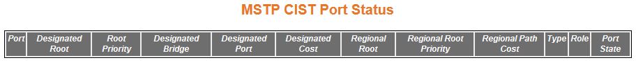
| Screen Objective |
This screen allows the user to view information
maintained by every port of the switch for CIST. |
| Navigation |
|
| Fields |
- Port—displays
the port, which is a combination of interface type and interface
ID. The interface ID is a combination of a slot number and a port
number (slot number/port number).
- Designated Root—displays the unique identifier
of the bridge recorded as the CIST root
in the transmitted configuration BPDUs. This value is an 8-byte
octet string. For example, 80:00:00:01:02:03:04:05
- Root Priority—displays the Bridge Priority
configured in Global Configuration Screen that represents the priority
of the bridge recorded as the CIST root
in the configuration BPDUs transmitted. This value ranges from 0
to 61440. The default value is 32768.
- Designated Bridge—displays the unique
identifier of the bridge, which the port considers to be the designated
bridge for the port's segment. The designated bridge is the only
bridge allowed to forward frames to and from the segment. This value
is an 8-byte octet string. For example, 80:00:00:01:02:03:04:05.
|
| Fields (cont) |
- Designated Port—displays
the identifier of the port on the Designated Bridge for the port's
segment. This represents the port through which the Designated Bridge forwards
frames to and from the segment. This value is a 2-byte octet string.
For example, 80:05.
- Designated Cost—displays the identifier
of the port on the Designated Bridge for the port's segment. This
represents the port through which the Designated Bridge forwards
frames to and from the segment. This value is a 2-byte octet string.
For example, 80:05.
- Regional Root—displays the unique identifier
of the bridge recorded as the CIST regional
root in the configuration BPDUs transmitted. This value is an 8-byte
octet string. For example, 80:00:00:01:02:03:04:05
- Regional Root Priority—displays the Bridge
Priority that represents the priority of the bridge recorded as
the CIST regional root in the
configuration BPDUs transmitted. This value ranges from 0 to 61440.
The default value is 32768.
- Regional Path Cost—displays the port’s
Path Cost that contributes to the cost of paths (including the port)
towards the CIST Regional Root.
This value ranges from 1 to 200000000.
- Type—displays the operational Point-to-Point
Status of the LAN segment attached to the port. The values can be:
- Point-to-point—port is treated as if it is connected to a point-to-point
link.
- SharedLan—port is treated as if it is having a shared media
connection.
Note: The User can set the values
directly or can set as Auto for the switch to decide about the point-to-point
status, in the field Point-to-Point Status provided in the screen CIST Settings.
- Role—displays
the current role of the port for the spanning tree instance. The values
can be:
- Disabled—specified that the port is disabled manually
(Port State) or automatically (Link status in Layer 2 Management
> Port Manager > Basic Settings). It does not take part in the spanning
tree process.
- Alternate—specifies that the port is acting as an alternate
path to the root bridge (i.e. it is blocked and not used for traffic).
The alternate port is enabled and declared as a root port if the
current root port is blocked.
- Backup—specifies that the port is acting as a backup path to
a segment where another bridge port already connects (i.e. it is
blocked and not used for traffic). The backup port is enabled and
declared as a designated port if the active designated port is blocked.
- Root—specifies that the port is used to forward data to root
bridge directly or through an upstream LAN segment.
- Designated—specifies that the port is used to send and receive
packets to/from a specific downstream LAN segment/device. Only one
designated port is assigned for each segment.
|
| Fields (cont) |
- Port State—displays
the current state of the port as defined by the common STP. The values can be:
- Disabled—specifies
that the port is disabled manually (Port State) or automatically
(Link). It does not take part in the spanning tree process.
- Discarding—specifies that the port is in Discarding state i.e.
No user data is sent over the port.
- Learning—specifies that the port is in the Learning state i.e.
the port is not forwarding frames yet, but is populating its MAC-address-table by learning source
addresses from received frames and storing them in the switching database
for using these details while sending and receiving data.
- Forwarding—specifies that the port is in Forwarding state i.e.
the port is operational by sending and receiving data based on the
formed spanning tree topology which is loop-free.
|
Bridge Priority
Figure 8. Bridge Priority

| Screen Objective |
This screen allows the user to configure the
bridge priority to be assigned to the specified VLAN. |
Note: Bridge Priority can be
configured only if MSTP Instance
is created using the VLAN Mapping
screen
|
| Navigation |
|
| Fields |
- Select—select
the MSTP Instance ID for which
the configuration needs to be applied.
- MSTP Instance ID—displays the integer
value that uniquely identifies an instance of the MSTP. This value ranges from 1
to 64. The special value 4094 is used in a switch that supports
PBB-TE. This special value represents PTETID that identifies VID,
which can be used by ESPs.
Note: This value is the instance ID
created using the VLAN Mapping
screen.Any external agent can separately provide ESPs. The ESPs
do not use spanning tree.
|
| Fields |
- Root—select
the root type for the given VLAN interface.
The list contains:
- primary—configures the switch to become
root for a given VLAN. The priority
of the switch is lowered until it becomes root
- secondary—configures the switch to become backup root for a
given VLAN. The priority of the
switch is lowered until it becomes one priority higher than the
root, so it can become root if the current root fails.
- Bridge Priority—denter the priority value
that is assigned to the switch. This value is used during the election
of CIST root, CIST regional root, and IST root. This value ranges from
0 to 61440. The default value is 32768.
Note: The value should
be set in increments of 4096. For example, 0, 4096, 8192, 12288,
and so on.
- Bridge Cost—displays the Cost of the
path to the MSTI Regional Root seen by this bridge. This is a read-only
field
- Root Port—displays the port number of
the port which offers the lowest path cost from this bridge to the CIST Root Bridge. This is a read-only
field
|
| Buttons |
- Apply—modifies
attributes and saves the changes.
|