All equipment must be installed according to
applicable local wiring codes and standards.
Always use cables
that are rated for the operating ambient temperature of 85°C.
For
100-240 VAC rated equipment, protection for earth fault is provided
by max. 20 A branch circuit from AC input in building installation.
The protection in the building installation is relied upon for short-circuit backup
protection.
- The specification for AC breaker is 5 A,
2P, 277 VAC (min) Circuit breaker, Thermomagnetic, or equivalent
type.
- The plug connector and wire gauge sizing is to be selected with
appropriate design as per the Electrical code for a 60W, 1-phase
device.
Note for IT power distribution systems:
- This
product is also designed for IT power distribution system with phase-to-phase
voltage 230 V.
- This equipment must be connected to an earthed mains socket-outlet.
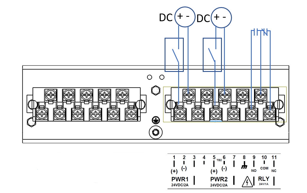
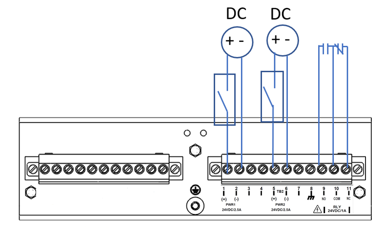
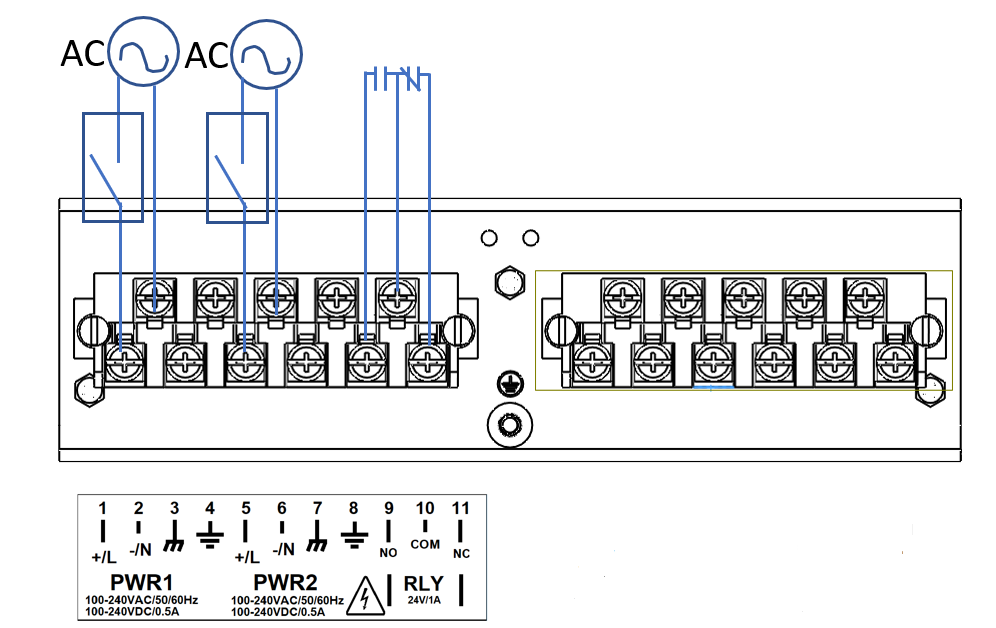
Figure 1. AC Wiring Diagram

|
L—stands for Live; N—stands for Neutral
NO—Normally
Open (open=open circuit=not creating a path for the current)
NC—Normally
Closed (open=short circuit=creating a path for the current)
PE—Protective
Earth (earth Ground point in the electrical circuit
|
To establish AC power connection with the power
source turned off, follow the steps below. When following the instructions,
refer to Figure 1.
- Remove the transparent plastic finger safe cover
from the face of the terminal block.
If an AC power supply has been installed in PS1, perform
steps 2 through 4 on the left hand terminal block. Please note that
if there are no DC power supplies installed on the iMR350 then the
right hand terminal block will not be populated.
- Connect the ground from the first power source to GND1
terminal screw (pin 4).
- Connect the Live from the first power source to the PWR1
+/L terminal screw (pin 1).
- Connect the Neutral from the first power source to the
PWR1 -/N terminal screw (pin 2).
If an AC power supply has been installed in PS2, perform
steps 5 through 7.
- Connect the ground from the second power source to GND2
terminal screw (pin 8).
- Connect the Live from the first power source to the PWR2
+/L terminal screw (pin 5).
- Connect the Neutral from the first power source to the
PWR2 -/N terminal screw (pin 6).
To keep the wires from pulling loose, use a small flat-blade
screwdriver to tighten the wire-clamp screws on the front of the
terminal block connector.
- After wiring is completed, reinsert the transparent plastic
finger safe cover back onto the face of the terminal block.
- Connect pin 3 to the ground of the chassis, with a braided
cable, if Power Supply 1 is in use.
- Connect pin 7 to the ground of the chassis, with a braided
cable, if Power Supply 2 is in use.