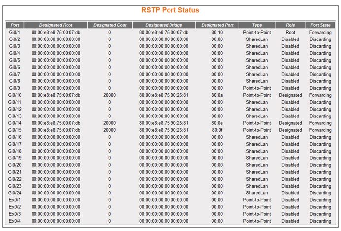
| Screen Objective |
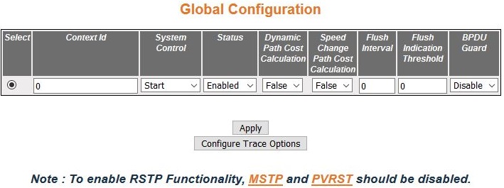
This screen allows the user to configure the
port information for RSTP used
during computation of loop-free topology. |
| Navigation |
|
| Fields |
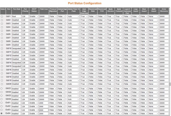
- Select—click
to select the port for which the configuration needs to be applied.
- Port—displays the port, which is a combination
of interface type and interface ID. The interface ID is a combination
of a slot number and a port number (slot number/port number).
Note: Only
the ports whose Admin State is set as Up are displayed.
- Port Role—displays the current role of
the port for the spanning tree. The values can be:
- Disabled—specifies
that the port is disabled manually (RSTP Status)
or automatically (Link). It does not take part in the spanning tree
process.
- Alternate—specifies that the port is acting as an alternate
path to the root bridge. It is blocked and not used for traffic.
It is enabled and declared as the root port if the root port is
blocked.
- Backup—specifies that the port is acting as a backup path to
a segment where another bridge port already connects. The port is
blocked and not used for traffic, and it is enabled and declared
as the designated port if the active designated port is blocked.
- Root—specifies that the port is used to forward data to root
bridge directly or through an upstream LAN segment.
- Designated—specifies that the port is used to send and receive
packets to/from a specific downstream LAN segment/device.
Only one designated port is assigned for every segment.
- Port Priority—enter the priority value
that is assigned to the port. This value is used during the Port
Role selection process. This value ranges from 0 to 240. The default
value is 128. This value should be set in steps of 16, e.g., 0,
16, 32, 48, etc.
- RSTP Status—select the administrative
module status requested by management for the RSTP Module on the port. This enables
or disables RSTP status of the
port. The default option is Enable. The list contains:
- Enable—enables RSTP in the device on the port.
The port participates in the STP process
and is ready to transmit/receive BPDUs
and data.
- Disable—disables RSTP in
the device on the port. The port does not participate in the STP process and is not ready to
transmit / receive BPDUs and data.
- Path Cost—enter the path cost that contributes
to the path cost of paths containing the port. The paths’ path cost
is used during calculation of shortest path to reach the root. The
path cost represents the distance between the root port and designated
port. This value ranges from 0 to 200000000. The default value is
200000 for all physical ports and 199999 for port channels.
|
| Fields |
Note: The default value is used as the path
cost if this field is not configured, and the Dynamic Path Cost
Calculation and Speed Change Path Cost Calculation are set as False. The
dynamically calculated path cost is used if the path cost is not
manually configured, and one of these Fields is set as True.The
configured value is used as the path cost irrespective of the status
(True or False) of the Dynamic Path Cost Calculation and Sped Change
Path Cost Calculation.The path cost value is calculated automatically
based on the port speed maintained by CFA module if the value is
set as 0.
- Protocol Migration—select
the protocol migration state of the port. This is used for controlling
of the protocol migration mechanism that enables the module to interoperate
with legacy 802.1D switches. The default option is False. The list contains:
- True—specifies that the port transmits BPDUs
based on the spanning tree protocol supported by the receiving switch.
The port is forced to transmit RSTP BPDUs.
- False—specifies that the port does not perform protocol migration
mechanism. The port always transmits the standard RSTP BPDUs.
Note: This
field cannot be configured if the RSTP Status
is set as Disable.The protocol migration triggers the transmission
of RSTP BPDUs
only once when set as True. The protocol migration changes automatically
as False, once the RSTP BPDU is transmitted.
- Admin Edge Port—select the administrative
status of the Edge Port parameter. The default option is False.
The list contains:
- True—sets the port as an edge port. The
Port State is immediately set as forwarding. It is connected directly
to a single end station. It allows RSTP to converge
faster and does not wait to receive BPDUs.
- False—sets the port as a non-Edge port. The spanning tree process
is performed using the RSTP.
It is connected to a routing device such as switch.
Note: The
value of the Edge Port parameter is automatically updated if the
Auto Edge Detection is set as True
- Admin Point-to-Point—select the administrative
point-to-point status of the LAN segment
attached to the port. The default option is Auto. The list contains:
- Forcetrue—specifies that port is connected to a point-to-point
link.
- Forcefalse—specifies that port is having a shared media connection.
- Auto—specifies that the ports as having a shared media connection,
or a point-point link based on the prevailing conditions.
Note: Port
is considered to have a point-to-point link if: - It is an
aggregator and all its members can be aggregated.
- The MAC entity is configured
for full Duplex operation, either manually or through auto negotiation
process (negotiation Mode is set as Auto).
|
| Fields (cont) |
|
| Fields (cont) |
- Layer 2-Gateway Port—select
whether the port acts as a normal port or as a L2GP. The default
option is False. The list contains:
- True—specifies that the
port operates as a Layer 2 Gateway Port.
- False—specifies that the port operates as a normal port.
Note: BPDU Transmit, Restricted Role
and Restricted TCN should be set
as False before configuring the port as a Layer 2 gateway port.
L2GP operates similarly to that of the normal port operation but
pretends to continuously receive BPDUs when Admin State is set to
Up.
- Loop Guard—select
the status of loop guard. The Loop Guard does age out the information
even if the peer does not send information. If the port continues
to receive information through BPDUs,
the operation on this port will be normal. This is useful when the
neighbor bridge is faulty; that is, the bridge cannot send BPDUs but continues to send data
traffic. The default option is False. The list contains:
- True—enables
the loop guard in the port.
- False—disables the loop guard in the port.
- Root Guard—select the administrative
status for the root guard feature in the port. When enabled, this
feature causes the port not to be selected as Root Port for the
topology, even if it has the best spanning tree priority vector.
Such a Port will be selected as an Alternate Port after the Root
Port has been selected. The default option is Disabled, and this
can cause lack of spanning tree connectivity. It is set by a network
administrator to prevent bridges external to a core region of the
network influencing the spanning tree active topology; possibly
because those bridges are not under the full control of the administrator.
- Enabled—enables root guard feature in the port.
- Disabled—disables root guard feature in the port.
Note: The
root guard feature can be enabled only for the ports whose Switch
Port Mode is configured as Trunk using Layer 2 Management > Port
Manager > Port Basic Settings screen.
- BPDU Guard—the administrative status
for the BPDU guard feature in
the port. This feature configures BPDU guard
globally in RSTP and this global BPDU is applicable if and only
if no port specific BPDU Guard
is configured. The default option is Disable. The list contains:
- Enabled—enables BPDU Guard
feature on edge ports globally and moves the port to disable discarding
state when BPDU is received on
the edge ports
- Disabled—disables BPDU Guard
feature on edge ports globally.
- Error Recovery—enter the amount of time
to bring the interface out of the error-disabled (err-disabled)
state. This value ranges from 30 to 65535 seconds. The default value
is 30.
|
| Buttons |
- Apply—modifies
attributes and saves the changes.
|