Use the Serial Profile Configuration dialog box to configure all parameters of a serial profile.
To access Serial Port Configuration screens, go to .
By default, the tab Serial Management displays the Serial Port Configuration screen.
Serial Profile Configuration
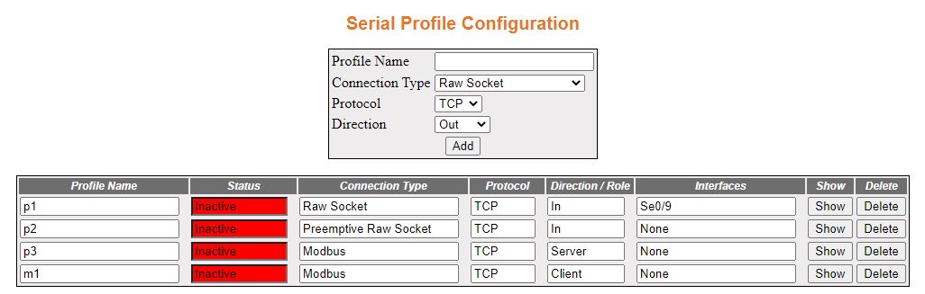
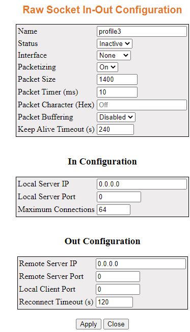
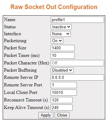
The add form in this page is dynamic. When Raw Socket connection type is selected, protocol and direction fields are shown. If a protocol is switched to UDP, direction will be hidden.
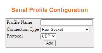
Raw Socket with UDP
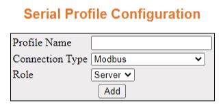
Finally, if Modbus connection type is selected, both protocol and direction fields will be hidden but a new field Role appears.
| Screen Objective | This screen allows the user to configure the Serial Profile Configuration Status. |
| Navigation |
|
| Profile Name | Enter the name of the profile. |
| Status | This field displays the status of the display. |
| Connection | This field displays / configures the connection type. The options are:
|
| Protocol | This field displays / configures the protocol type. The options are: |
| Direction / Role | This field displays / configures the direction
for a serial protocol. Select one of the following options:
|
| Interfaces | This field displays details about the serial interface. |
| Buttons |
|
Use the Show button display a configuration panel on the right side of page to edit the given profile. Each page will include a Close button for exiting the Serial Profile Configuration panel. The following options are available.
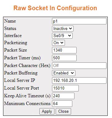
| Screen Objective | This screen allows the user to apply the Serial Profile Configuration. |
| Name | This field displays the profile name. |
| Status | This field configures the status of the profile. The options are:
|
| Interface | This field configures the interface for the profile. The options are:
|
| Packetizing | This field configures the status of the packetizing feature. The options are:
|
| Packet Size | Enter a value for packet size. The range is from 16 to 1400. The default value is 1400. |
| Packet Timer (ms) | Enter a value for the delay between the packets sent from serial ports. The range is from 0 to 1000. The default value is 10 ms. |
| Packet Character (hex) | Enter a value for the delay between the packets sent from serial ports. The range is from 0 to 255. The default value is 10 ms. Or configure it as OFF to disable packet character feature. This is the default option. |
| Packet Buffering | This field configures the status of the packet buffering feature. The options are:
|
| Local Server IP | Enter a local server IP address. |
| Local Server Port | Enter a value for the local port number. Port numbers range between 15010 to 15110. For Modbus, the software internally assigns 502 TCP port number if an user configures modbus as its port. |
| Keep Alive Timeout (s) | Enter a value for the time which specifies how long the device will wait for a response to keep alive packets sent before terminating the TCP connection The range is from 60 to 600. The default value is 240 s. |
| Maximum Connections | Enter a value for the maximum number of allowed incoming TCP connections. The range is from 1 to 64. The default value is 64. |
| Buttons |
|


Some extra parameters shown in the Raw Socket UDP Configuration interface are as shown below.
| Screen Objective | This screen allows the user to apply the Raw Socket UDP Configuration. |
| Server IP | Enter a local server IP address. |
| Server Port | Enter a value for the server port number. |
| Remote Connections | Enter a value for the maximum number of allowed incoming TCP connections. The range is from 1 to 64. The default value is 64. |

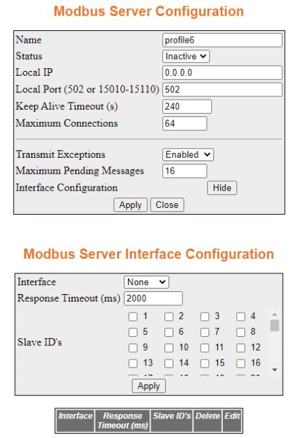
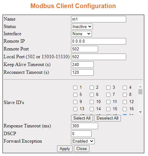
Some extra parameters shown in the Modbus Configuration interface are as shown below.
| Screen Objective | This screen allows the user to apply the Modbus Server / Client Configuration. |
| Transmit Exceptions | Select an option to enable / disable sending TCP exception back to the master if a response has not been received from RTU within the expected time.
|
| Maximum Pending Messages | Enter a value for the maximum number of messages that Modbus server can handle from different clients. The range is from 0 to 16. The default value is 16. |
| Interface Configuration | If needed, select the button Configure. When this option is selected, the Modbus Server Interface Configuration dialog box appears which has the following parameters as shown below. |
| Interface | This field configures the interface for the profile. The options are:
|
| Response Timeout (ms) | Enter a value for the time to wait for a response from a serial port. The range is from 50 to 10000. The default is 2000 ms (as shown in the figure). |
| Slave ID’s | Enter a value for the slave ID. The format is comma separated integer values with a maximum of 10 slave IDs per command. The range is from 1 to 247. For Modbus Client Configuration, there two extra buttons as follows:
|
| DSCP | Enter a value decimal value for the Differentiated service code point (DSCP) which is set in the IP header for the outgoing packets. The range is from 0 to 63. The default is 0 (as shown in the figure). |
| Forward Exception | Select an option to enable / disable forwarding TCP exception back to the master if a response has not been received from RTU within the expected time. |