UFD (Uplink
Failure Detection) allows a device to detect a link failure on uplink
interfaces and to propagate the failure to the downlink interfaces
so that servers connected to those downlink interfaces can switch
over to secondary interfaces.
The UFD feature allows the
administrator to create groups that contain a set of uplink interfaces
and Raptor to monitor uplink interfaces to spot link failures. and
a set of downlink interfaces to disable.
UFD supports network adapter
teaming and provides network redundancy. In network adapter teaming, all
network interface cards on a server are configured in a primary
or secondary relationship and share the same IP address. When the
primary link goes down, the server transparently shifts the connection
to the secondary link. The primary and secondary links are connected
to two switches each supporting uplink failure detection UFD feature.
When UFD is enabled, the switch
monitors uplink interfaces for link failures. When the switch detects
a link failure, the switch disables the downlink interfaces— one
of which is connected to the server. When the server detects disabled
downlink interfaces, it switches over to the secondary link connected
to another switch to ensure that there is another path for the traffic
flow.
To access UFD screen, click .
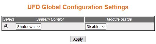
UFD Global Configuration Settings
Figure 1. UFD Global Configuration Setting
| Screen Objective |
This screen allows the user to configure the
UFD global settings. |
| Navigation |
|
| Fields |
- System Control—select
the administrative system control status of the UFD module. The default option is
Shutdown. The list contains:
- Start—starts the UFD feature in the system, only
when any one uplink port is in admin and operationally in “UP” state
in the group.
- Shutdown—shuts down the UFD feature
in the system, only when all uplink ports within the group is in
admin and operationally “DOWN”, or no uplink ports are assigned
in the group.
- Module Status—select the administrative
module status of the UFD module.
The default option is Disable. The list contains:
- Enable—enables
the UFD feature in the system.
- Disable—disables the UFD feature
in the system.
|
| Buttons |
- Apply—modifies
attributes and saves the changes.
|
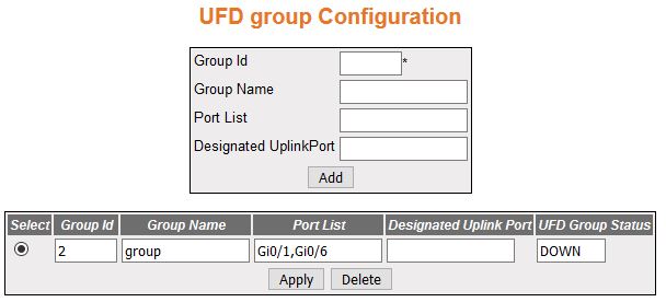
UFD Group Configuration
Figure 2. UFD Group Configuration
| Screen Objective |
This screen allows the user to configure the UFD group configuration settings. |
| Navigation |
|
| Fields |
- Select—click
to select the group id for which the configuration need to be applied or
deleted.
- Group ID—enter the group identifier that
uniquely identifies the group. Each group has uplink interfaces
to monitor and downlink interfaces to disable. The UFD group ID value zero indicates
that the port is not present in any group. By setting the UFD Group ID value to zero, the
port will be removed from the UFD group
to which it belongs to. This value ranges from 0 to 65535.
|
| Fields |
- Group Name—enter
the name of the UFD group. This
Group Name is a string of maximum size 32.
Note: The Group Name
should be only characters—no numerical symbols allowed.
- Port List—enter the port list for UFD group name.
- For interface
type other than internal-land and port-channel, this value is a combination
of slot number and port number separated by a slash.
- For interface types internal-lan and port-channel, only i-lan
or port-channel ID is provided.
Use comma as a separator
without a space while configuring list of interfaces. For example:
0/1, 0/3 or 1, 3
- Designated Uplink Port—enter the port
that is termed as designated uplink when the port is connected to
the network and it has more preference to a particular set of uplink
ports. Broadcast/unknown multicast use this designated port to reach
uplink.
- For interface type other than internal-land and
port-channel, this value is a combination of slot number and port
number separated by a slash.
- For interface types such as internal-lan and port-channel, only
i-lan or port-channel ID is provided.
Use comma as a
separator without a space while configuring list of interfaces.
For example: 0/1, 0/3 or 1, 3
- UFD Group Status—displays the UFD group status. The default value
is DOWN. The list contains:
- UP—specifies the status of the
group as 'UP', only when any one uplink port is in admin and operationally
'UP' state in the group.
- DOWN—specifies the status of the group as 'DOWN', only when
all uplink ports within the group is in admin and operationally
'DOWN' or none uplink ports assigned in the group.
|
| Buttons |
- Apply—modifies
attributes and saves the changes.
- Delete—deletes the selected entry.
|