This section describes how to configure Rapid Spanning Tree Protocol (RSTP) on the switch.
RSTP (Rapid Spanning Tree Protocol) is a portable implementation of the IEEE 802.1D standard. It provides rapid recovery of connectivity following the failure of a bridge/bridge port or a LAN. It reduces the time for reconfiguring the active topology of the network when physical topology or topology configuration parameters change. It provides increased availability of MAC service when there is a reconfiguration or failure of components in a bridged LAN. It can inter-operate with legacy STP bridges without any change in the configuration. This is the switch’s default spanning tree algorithm.
- High availability
- Executing multiple instances of the protocol
- Provider bridging
To access RSTP screens, go to .
Global Information
By default, the tab Global Settings displays the Global Configuration screen.

| Screen Objective | This screen allows the user to configure for each available virtual context the MST module parameters that are used globally in the switch for all ports. |
Note:
To enable RSTP, MSTP and PVRSTP should be disabled in the selected context. |
|
| Navigation |
|
| Fields |
|
| Fields (cont) |
|
| Buttons |
|
RSTP Traces
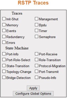
| Screen Objective | This screen allows the user to enable the required debug statements for RSTP module that will be useful during debug operation. |
| Navigation | screen. Click Configure Trace Options. |
| Fields |
|
| Fields (cont) |
|
| Buttons |
|
RSTP Configuration

| Screen Objective | This screen allows the user to configure the bridge priority to be assigned to the specified VLAN. |
Note:
Bridge Priority can be configured only if MSTP Instance is created using the VLAN Mapping screen |
|
| Navigation |
|
| Fields |
|
| Fields |
|
| Buttons |
|
Port Status Configuration

| Screen Objective | This screen allows the user to configure the port information for RSTP used during computation of loop-free topology. |
| Navigation |
|
| Fields |
|
| Fields | Note:
The default value is used as the path cost if this field is not configured, and the Dynamic Path Cost Calculation and Speed Change Path Cost Calculation are set as False. The dynamically calculated path cost is used if the path cost is not manually configured, and one of these Fields is set as True.The configured value is used as the path cost irrespective of the status (True or False) of the Dynamic Path Cost Calculation and Sped Change Path Cost Calculation.The path cost value is calculated automatically based on the port speed maintained by CFA module if the value is set as 0.
|
| Fields (cont) |
|
| Fields (cont) |
|
| Buttons |
|
RSTP Port Status
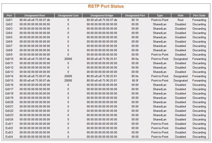
| Screen Objective | This screen allows the user to view information maintained by every port of the switch for RSTP. |
| Navigation |
|
| Fields |
|
| Fields (cont) |
Note:
The values can be set directly or as Auto for the switch to decide about the point-to-point status, in the field Admin Point to Point provided in the screen Port Status Configuration.
|