This section describes the CLI commands used to configure the MRP feature.
Media Redundancy Protocol (MRP) is a networking protocol designed to implement redundancy and recovery in a ring topology. MRP is designed to react deterministically on a single failure on a switch in the MRP ring. An MRP instance is configured between two ports known as ring ports and can act as manager or client in the ring. The MRP node which is configured as manager has the responsibility of avoiding the loop in the ring by making one ring port as blocking and other as forwarding. The convergence time of MRP is very fast as compared to spanning tree protocols. On a port either MRP can be enabled or spanning tree may be selected.
To configure MRP, first it needs to be enabled at the global level, the instance needs to be created with required mode and then instance needs to be mapped to the ring ports, this chapter describes the commands used.
Note: To enable an MRP ring instance on a port; first spanning tree needs to be disabled. Both protocols cannot run together on the same port.
Redundancy
Redundancy within the network considers the presence of more network elements (switches, link) than necessary operation, in order to prevent the loss of communication caused by a failure. To effect this, there is more than one physical path between any two nodes. IEC 61918 specified ring topology, every switch has a redundant connection (link) into the network. the redundant links are not required for a failure-free/normal operation of the network. In case of a failure, these redundant links are used to prevent the breakdown of the network. The disadvantage of ring topology is that, it can introduce a “packet loop” that creates broadcast storms in the network.
Spanning Tree protocols, such as RSTP, specify a method for providing media redundancy while preventing the undesirable packet loop in a network (i.e.) RSTP were developed to detect and eliminates the physical loop in the network. Also, in case of a failure in the network, a topology change notification is sent out to create a different safe path.
Although STP is effective enough for many networks, it takes longer time for re-convergence in case of failure. This is not good enough for mission-critical industrial Ethernet applications. To overcome the limitations of RSTP, MRP protocol was developed. MRP uses mechanisms similar to RSTP (e.g., delete forwarding database after reconfiguration, set ports into blocking or forwarding mode), but it takes lesser time for re-convergence in case of failure. Below is the comparison of MRP with RSTP.
| MRP | RSTP | |
|---|---|---|
| Topology | Ring | Any |
| Number of Switches | Up to 50 switches to meet the 200ms reconfiguration requirement. | Maximum of 40 Switches |
| Recovery Time | Recovery time in case of a failure can run into Less than 200ms | Recovery time in case of a failure can run into seconds depending on the topology and size of the network. |
| Configuration | Simple | Medium |
MRP
An MRP-compliant network shall have a ring topology with multiple nodes. According to IEC 62439-2, One of nodes in the network takes on the role of the redundancy manager (MRM), the other nodes are the redundancy clients (MRC). The ports at a node which are connected with the subsequent or preceding node are named ring ports.
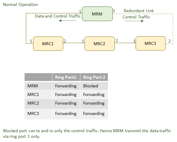
It is the Redundancy Manager’s responsibility to monitor the ring topology. During normal ring operation (i.e., no link or node failure in the ring topology) the Redundancy Manager disconnects one of its ring ports, so that the ring topology becomes ‘loop free’ from a communication point of view. As soon as the ring is open due to the failure of a node, and the data communication is broken, the Redundancy Manager reconfigures the data paths within 200ms. It enables the disconnected ring port and creates a new loop free topology.

To detect errors in the network, the redundancy manager sends MRP_Test frames on both of its ring ports. These frames run through the ring in both directions until they arrive at the other ring port of the manager. These MRP_Test frames are marked with a special MAC address and forwarded by the MRCs only to the opposite ring ports. They are sent periodically every MRP_Test default interval (20 ms by default). If the MRP_Test frames arrive on both ends back to the MRM, the ring is detected as defect free(ring closed) and the MRM blocks the loop. This is done by changing the state to BLOCKED at one of the ring ports in the MRM and the other as FORWARDING as shown in Figure 2 below. On this BLOCKED port only test frames to supervise the ring (MRP_Test frames) are sent. Data frames are sent by the MRM only on the port in the FORWARDING state.
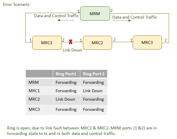
If MRP_Test frames, typically 3 frames in sequence of are not received by the MRM, the ring topology is considered as interrupted. So it takes 60 ms to detect a failure in the ring. To change the topology in the whole ring, all MRCs and the MRM have to clear their FDBs at the same time as the redundant port is changing state from BLOCKED to FORWARDING to keep the network consistent. The MRM sends 3 MRP_TopologyChange messages in 10ms delay into the ring with the indication that the topology has changed. The blocked port on the MRM changes the state from BLOCKING to FORWARDING. Every MRC receiving MRP_TopologyChange indications is supposed to clear its Filtering Data Base (FDB) at the MRP_TOPchgT time. Afterwards it has to build up again the FDB based on the new topology.
The time between detecting a ring interruption and restoring a new data structure is referred to as the recovery time. The recovery time has a maximum value of 200ms. As soon as the fault is recovered in the network, the redundancy manager disconnects its ring port again and informs the clients of the change.
Alarms supported in MRP
Alarms are raised for various events that occur in the device. Alarms for the events in MRP are grouped under protocols. As defined in the PRD document, the following alarms are supported for events associated with MRP.
iS5Comm# sh alarm supported all

The alarm is raised with set whenever there is a change in the ring status. This event can occur whenever there is a change in ring status. i.e., ring is closed or opened due to changes in topology or configuration. When the ring state machine is disabled, the alarm is cleared.
# sh alarm history protocol

The alarm is raised when the ring node detects more then one manager nodes in the network. The alarm will be cleared when this condition is cleared.