This section describes how to configure Link Aggregation
(LA).
Link Aggregation (LA) implements the LA functionality as per the IEEE
802.3ad standard. LA feature allows
the user to combine individual point-to-point links into a LA group. A MAC client
treats the LA group as a single
link. The total capacity of the LA group
is the sum of the capacities of the individual links present in
the group. The LA group provides
increased bandwidth for the traffic between the hosts and the server,
and it does not affect the traffic if any of the links are made
down.
LA feature is supported only
in point-to-point links, with MACs
operating in full Duplex mode. All links in a LA group
should work at the same data rate (i.e. speed should be same).
The switch supports up to 8 link aggregation groups, each link
aggregation group may support up to a maximum of 8 ports.
To access Link Aggregation screens, click .
Basic Settings
By
default, the tab Basic Settings displays
the Link Aggregation Basic Settings screen.
Figure 1. Link Aggregation Basic Settings

| Screen Objective |
This screen allows the user to configure the
Link Aggregation (LA) module parameters that
are used globally in the switch for all ports available in it. |
| Navigation |
|
| Fields |
- System Control—select
the system control status of the LA in
the switch. The default option is Start. The list contains:
- Start—starts
the LA module and allocates the
resources required by the LA.
- Shutdown—shuts down the Link Aggregation module and releases
the allocated resources to the system.
Note: All fields
in this screen are greyed out when System Control is Shutdown.
- LA Status—select the administrative status
of the LA module. The LA feature allows the user to aggregate
individual point-to-point links into a LA group.
The default option is Disabled. The list contains:
- Enabled—enables LA on all ports in the switch. The LA is enabled in the switch, only
if the LA System Control is set
as start.
- Disabled—disables LA in the
switch on all ports.
- System Priority—enter the priority value
associated with the system’s ID. This value ranges from 0 to 65535.
The default value is 32768.
- System ID—enter 6-octet unicast MAC address value that is used as
a unique identifier for the switch containing the aggregator. The
default value is 00:01:02:03:04:01.
- LA Independent Mode—select the independent
mode of the LA module. The default
option is Disabled. The list contains:
|
| Buttons |
- Apply—modifies
attributes and saves the changes.
|
Port Channel Interface Basic
Settings
Figure 2. Port Channel Interface Basic Settings

| Screen Objective |
This screen allows the user to create a port
channel (aggregator) and configure the port channel related parameters.
The port channel is treated as a logical port that is used to aggregate
several ports. The port channel related parameters are configured on
context basis. |
Note: The port channel should
be created, and its related parameters should be configured, before aggregating
the ports. The port channel can be created, only if the System Control
is set to Start in Link Aggregation Basic Settings.
|
| Navigation |
|
| Fields |
- Port Channel ID—enter
the identifier that uniquely determines a port channel to be created
in the switch. This value ranges from 1 to 65535.
- Context—select the context ID. Context
of 0 is available for the current version.
- Admin Status—select the desired Admin
status of the port channel. The default option is Up. The list contains:
- Up—allows the port channel to be available for aggregating the
ports and transmitting / receiving traffic.
- Down—blocks the availability of the port channel for aggregating
the ports and transmitting / receiving traffic.
- Operational State—select the context
ID. Context of 0 is available for the current version.
- Up—port
channel is available for aggregating ports and transmitting / receiving
traffic.
- Down—port channel availability for aggregating ports and transmitting
/ receiving traffic is blocked.
|
| Fields (cont) |
- MTU—enter the MTU for the port channel. This value
defines the largest PDU that can
be passed by the channel without any need for fragmentation. The
default value is 1500. This value ranges from 46 to 9216.
Note: enter
the MTU for the port channel.
This value defines the largest PDU that can
be passed by the channel without any need for fragmentation. The
default value is 1500. This value ranges from 46 to 9216.
|
| Buttons |
- Add—adds and
saves new configuration.
- Reset—resets to default value for respective
fields and discards all user inputs.
- Apply—modifies attributes and saves the
changes.
- Delete—deletes the selected entry.
|
Port Channel Settings
Figure 3. Port Channel Settings
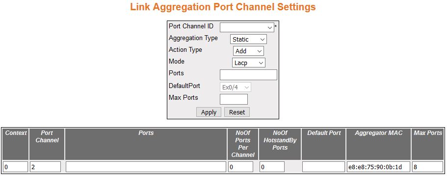
| Screen Objective |
This screen allows the user to add or delete
aggregation of ports, Distributed Link aggregation, and configure
their related parameters for the port channels already created in
the Port Channel Interface Basic Settings screen. |
Note: Only one entry can be
created for each port channel.The parameters in the screen are not
populated with values (the screen is blank) if the Link Aggregation’s
variable System Control is set as Shutdown
|
| Navigation |
|
| Fields |
- Context—displays
the virtual context ID that uniquely represents a virtual switch created
in the physical switch.
Note: The user can create new virtual
contexts from the Switch Creation screen. Go to Context Manager->Switch
Creation.The user can create new virtual contexts from the Switch
Creation screen.
|
| Fields (cont) |
- Port Channel ID—select
the port channel identifier from the list already specified in the
system, to which the ports should be aggregated or from which aggregated ports
should be removed. The list contains the port channels created in
the Port Channel Interface Basic Settings screen.
- Aggregation Type—select the type of aggregation
to be used in the port channel. The default option is Static for
all ports and Dynamic for the port configured as a default port
of the port channel. The list contains:
- Static—allows the
port to participate only in static aggregation; that is, the port
is a member of only the port channel to which it is configured.
The port channel should be manually assigned with its member ports.
- Dynamic—allows the port to participate only in dynamic aggregation
selection, that is, the port is made as a part of best aggregation
selected based on System ID and Admin key (that is, Port Channel
ID).
- Action Type—select the action to be performed
for the Ports configured in this screen. The default option is Add.
The options are:
- Add—aggregates the mentioned Ports and configures
them as a member for the selected Port Channel ID.
- Delete—removes the mentioned Ports from the member list created
for the selected Port Channel ID.
Note: The field is
greyed out when the aggregation type is set as Dynamic.
- Mode—select the operating mode to be
set for the port channel. The default option is Lacp. The list contains:
- Lacp—sets the port channel into passive negotiation state, in
which the port channel waits for its peer to initiate negotiation.
- Manual—sets/forces the port channel to enable channeling without
waiting for its peer to start negotiation.
- Disable—disables the channeling i.e. the LACP feature
is disabled in the port channel.
Note: The field is
greyed out when the aggregation type is set as Dynamic.
- Ports—enter port or set of ports, which
should be aggregated and set as member of the selected port channel.
Use a comma as a separator between the ports while configuring a
list of ports. The format of this entry is <interface type><slot number/port
number>. Note that here is no space needed between these two entries.
Example: Gi0/1,Gi0/2 (Here Gi is interface type Gigabit Ethernet
Interface, 0 is a slot number, and 1 is a port number). The maximum
number of ports is 8.
Note: The field is greyed out when the aggregation
type is set as Dynamic.
- No of Ports Per Channel—displays the
number of ports that are bundled for the port channel. For example,
this value would be set as 3, if the value for the field Ports is
entered as gi0/4,gi0/7,gi0/8.
- No of Hot Standby Ports—displays the
number of ports that are bundled for the port channel. For example,
this value would be set as 3, if the value for the field Ports is
entered as gi0/4,gi0/7,gi0/8.
|
| Fields (cont) |
- Default Port—select
the port that should be set as default port, which gets attached
to the port channel and participates only in dynamic aggregation
selection.
Note: This field is disabled (that is greyed out) and
cannot be configured, if the Aggregation Type is set as Static.
- Aggregator MAC—displays the 6-octet MAC address that is assigned to
the port channel. This MAC address is automatically assigned to
the port channel.
- Max Ports—enter the maximum number of
ports that can be attached to the port-channel. This value ranges
from 2 to 8. The default value is 8. If the total number of ports
attached to the port-channel exceeds the configured value, the best
ports are maintained in active state and other ports are maintained
in standby state. The best ports are calculated based on the Port
Identifier and Port Priority.
|
| Buttons |
- Apply—modifies
attributes and saves the changes.
- Reset—resets to default value for respective
fields and discards all user inputs
|
Link Aggregation Port
Settings
Figure 4. Link Aggregation Port Settings
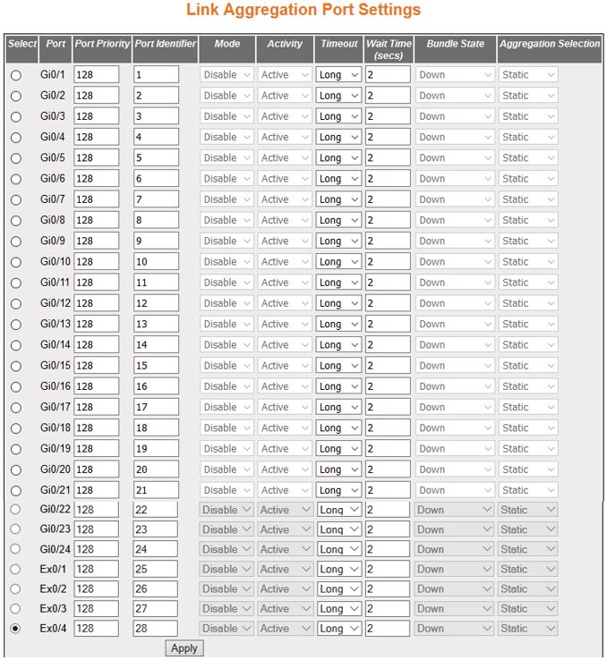
| Screen Objective |
This screen allows the user to configure the
Link Aggregation control configuration parameters for each port
in the switch. These parameters allow you to control the bundling
of physical ports. |
Note: The parameters in the screen
are not populated with values (the screen is blank) if the Link Aggregation
System Control is set as Shutdown.
|
| Navigation |
|
| Fields |
|
| Fields (cont) |
- Bundle State—displays
the current state of the port with respect to Link Aggregation.
This field is read only.
- Up In Bundle—specifies that the
port is an active member of the port channel. The port is operationally
up and actively takes part in aggregation.
- Standby—specifies that the port is a member of the port channel
but is currently in standby state. The port is capable of joining
in the port channel, when any of the ports in the port channel goes
down.
- Down—specifies that the port is operationally down in lower
layers or the port is operational in lower layers, but temporarily
it is not able to participate in aggregation because of different
partner information in the same group.
- Up Individual—specifies that the port is operating individually
and is not taking part in aggregation.
- Aggregation Selection—displays the type
of aggregation in which the port participates. The default option
is Static for all ports and Dynamic for the port configured as a
Default Port of the port channel. This field is read only.
- Static—allows
the port to participate only in static aggregation; that is, the port
is a member of only the port channel to which it is configured,
i.e. the port channel has to be assigned manually to its member
ports in the Link Aggregation Port Channel Settings screen.
- Dynamic—allows the port to participate only in dynamic aggregation
selection; that is, the port is made as a part of best aggregation
selection based on System ID and Admin key (i.e. Port Channel ID).
|
| Buttons |
- Apply—modifies
attributes and saves the changes.
|
Link Aggregation
Port State Machine Information
Figure 5. Link Aggregation
Port State Machine Information

| Screen Objective |
This screen allows the user to view the aggregation
state of the port channels created in the switch through the Port
Channel Interface Basic Settings screen. |
Note: The parameters in the screen
are not populated with values (the screen is blank) if the Link Aggregation
System Control is set as Shutdown.
|
| Navigation |
|
| Fields |
- Port Channel—displays
the identifier that uniquely identifies a port channel created in
the switch. This value ranges from 1 to 65535.
- Port Id—displays the port, which is a
combination of interface type and interface ID. The interface ID
is a combination of slot number and the port number (slot number/port
number).
- Aggregation State—displays the Actor
State as transmitted by the actor in LACPDUs. The state can be:
- Aggregation—sets
the port as a potential candidate for aggregation.
- Individual—does not set the port from aggregation. It can be
operated only as an individual link.
- Sync—allocates the port to the correct Link Aggregation group
which is associated with a compatible port channel whose identity
is consistent with the Actor System ID and Admin key (Port Channel
ID). The System ID and Admin Key are in sync with partner information.
- Collecting—enables the port to collect incoming frames and is
not expected to be disabled in the absence of administrative changes
or changes in received protocol information.
- Distributing—enables the port to distribute outgoing frames.
- Defaulted—sets the ports receive machine to use the default
operational partner information that is administratively configured
for the partner.
- Expired—sets the ports receive machine in expired state. The
receive machine state is changed as expired if the PDUs are not received from partner
for certain time period.
|
Link Aggregation Load Balancing
Policy
Figure 6. Link Aggregation Load Balancing Policy
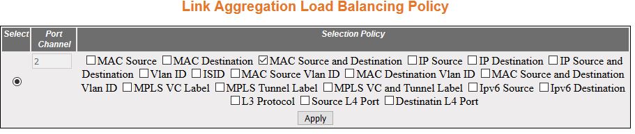
| Screen Objective |
This screen allows the user to configure the
rule for distributing the Ethernet traffic among the aggregated
links and establish load balancing. |
Note: The parameters in the screen
are not populated with values (the screen is blank) if the Link Aggregation
System Control is set as Shutdown.
|
| Navigation |
|
| Fields |
- Select—click
to select the port channel for which the configuration needs to
be done.
- Port Channel—displays the identifier
that uniquely identifies a port channel created in the switch. This
value ranges from 1 to 65535.
- Selection Policy—select the rule for
distributing the Ethernet traffic. The default option is MAC Source
and Destination. The options are:
- MAC Source—uses the bits
of the source MAC address in the
packet to select the port in which the traffic should flow.
- MAC Destination—uses the bits of the destination MAC address in the packet to select
the port in which the traffic should flow.
- MAC Source and Destination—uses the bits of the source and destination MAC address in the packet to select
the port in which the traffic should flow.
- IP Source—uses the bits of the source IP address in the packet
to select the port in which the traffic should flow.
- IP Destination—uses the bits of the destination IP address in
the packet to select the port in which the traffic should flow.
- IP Source and Destination—uses the bits of the source and destination
IP address in the packet to select the port in which the traffic
should flow.
- VLAN ID—uses the VLAN ID
in the packet to select the port in which the traffic should flow.
- ISID—uses the ISID in the packet to select the port in which
the traffic should flow.
- MAC Source VLAN ID—uses the VLAN ID
and source MAC address in the packet
to select the port in which the traffic should flow.
- MAC Destination VLAN ID—uses the VLAN ID
and destination MAC address in
the packet to select the port in which the traffic should flow.
- MAC Source and Destination VLAN ID—uses
the VLAN ID, source MAC address, and destination MAC address in the packet to select
the port in which the traffic should flow.
- MPLS VC Label—uses the MPLS VC
label in the packet to select the port in which the traffic should
flow.
- MPLS Tunnel Label—uses the MPLS tunnel
label in the packet to select the port in which the traffic should
flow.
- MPLS VC and Tunnel Label—uses the MPLS VC
and tunnel labels in the packet to select the port in which the
traffic should flow.
- Ipv6 Source—uses the bits of the source IPv6 address in the
packet to select the port in which the traffic should flow.
- Ipv6 Destination—uses the bits of the destination Ipv6 address
in the packet to select the port in which the traffic should flow.
- L3 Protocol—uses the frames of the L3 IP header in the packet
to select the port in which the traffic should flow.
|
| Fields |
- Selection Policy—The
options are (cont):
- L3 Protocol—uses the frames of the L3
IP header in the packet to select the port in which the traffic
should flow.
- Source L4 Port—uses the bits of L4 source port specified in
L4 header (TCP/UDP port) in the packet to select
the port in which the traffic should flow.
- Destination L4 Port—uses the bits of L4 destination port specified
in L4 header (TCP/UDP port) in the packet to select
the port in which the traffic should flow.
|
| Buttons |
- Apply—modifies
attributes and saves the changes.
|
DLAG Remote Port Channel
Information
Figure 7. DLAG Remote Port Channel Information
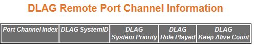
| Screen Objective |
This screen allows the user to view the details
of all remote port channels that are part of same D-LAG (Distributed Link Aggregation). |
Note: The parameters in the screen
are not populated with values (the screen is blank) if the Link Aggregation
System Control is set as Shutdown.
|
| Navigation |
|
| Fields |
- Port Channel Index—displays
the Remote Aggregator's interface index.
- DLAG System ID—displays the 6-octet MAC address value of each remote
D-LAG node and the system ID in D-LAG nodes
used for communicating with peer nodes.
- DLAG System Priority—displays stored
system priority of remote D-LAG nodes.
- DLAG Role Played—displays system priority
in D-LAG nodes which is to be
used for communicating with the peer node when D-LAG status is enabled. The list contains:
- none—specifies the role by the remote D-LAG node
as none.
- Master—specifies the role by the remote D-LAG node
as master.
- slave—specifies the role by the remote D-LAG node
as slave.
- backupmaster—specifies the role of a remote D-LAG node as backup-master
|
| Fields |
- DLAG Keep Alive Count—displays
the Keep Alive Count when D-LAG status
is enabled. Each D-LAG node
will have a Max Keep alive count and each D-LAG node maintains
separate keep alive counts for all other remote D-LAG nodes. The default value
is 3.
|
DLAG Remote Ports Information
Figure 8. DLAG Remote Ports Information

| Screen Objective |
This screen is used to access the stored port
list information of each remote D-LAG node |
Note: The parameters in the screen
are not populated with values (the screen is blank) if the Link Aggregation
System Control is set as Shutdown.
|
| Navigation |
|
| Fields |
- Port Channel Index—displays
the Remote Aggregator's interface index.
- DLAG System ID—displays the 6-octet MAC address value of each remote D-LAG node, which uniquely identifies
the remote.
- DLAG Remote Port Index—displays stored
system priority of remote D-LAG nodes.
- DLAG Remote Port Bundle State—displays
port bundle states of each port belonging to the remote DLAG node. The list contains:
- upInBndl—sets
the port operationally up and actively takes part in aggregation.
- standby—sets the port that is capable of joining in aggregation
group, when any of the ports in aggregation group goes down.
- down—sets the port operationally down in lower layers, or the
port is operational in lower layers but temporarily not able to
participate in aggregation because of different partner information
in the same group.
- upIndividual—sets the port to operate individually and not take
part in aggregation.
- DLAG Remote Port Index—displays the current
sync status of each port belonging to the remote DLAG node.
- inSync—sync
status of the port belonging to DLAG node
is inSync.
- outofSync— sync status of the port belonging to DLAG node is out-of-sync.
|