This section describes how to configure VLANs.
VLAN (Virtual LAN) module logically segments the shared media LAN to form virtual workgroups. It fully utilizes the forwarding support available in the switch hardware. It redefines and optimizes the basic transparent bridging functionalities, such as learning, forwarding, filtering, flooding, etc.
- Transparent bridging—allows the user to connect two similar network segments to each other at the data link layer in a manner transparent to end stations, so the end stations do not participate in the bridging algorithm.
- VLAN aware bridging—allows the end stations at different LAN segments to be interconnected and to communicate with each other using VLANs. It provides the following optional capabilities that are not available for the transparent bridging mode of operation:
- High availability (HA)—a feature for enhancing the network resiliency by minimizing the network downtime by integrating failover systems. VLAN in active node synchronizes the database with standby node(s).
- Multiple instances—multiple switch instances can be created within a physical switch. Different instances are identified using context ID.
- Provider bridging—supports IEEE 802.1ad standard.
To access VLAN Screens, click .
VLAN Basic Settings
By default, the tab Basic Settings displays the VLAN Basic Settings screen.
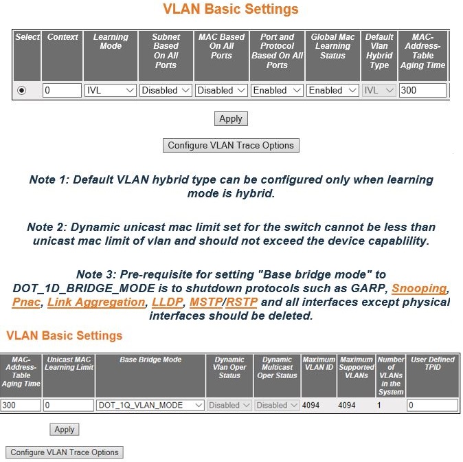
| Screen Objective | This screen allows the user to configure, for all available virtual contexts, the VLAN details that are used globally in the switch for all ports available in the switch. It allows the user to set the parameters such as VLAN type, which are fundamental for the VLAN configuration in the switch. |
Note:
When all VLAN type-related fields subnet based on all ports, MAC-based on all ports, and port and protocol based on all ports are set as Enabled, the VLAN membership classification is done in the following order:
|
|
| Navigation |
|
| Fields |
|
| Fields (cont) |
|
| Fields (cont) | Note:
Once the learning mode is changed:
|
| Fields (cont) |
The
DOT_1D_BRIDGE_MODE operates over the physical interface alone, so
all other VLAN / tunnel interfaces should be deleted.
|
| Fields (cont) | Note:
The VLAN ID 4095 is reserved and may be used to indicate a wildcard match for the VLAN ID in management operations or Filtering Database entries. VFI IDs 4096 and 4097 are reserved identifiers used in MPLS PW. The theoretical maximum for the maximum number of VFI is 65535 but the actual number of VFI supported is a sizing constant. Based on this, the maximum number of VFI ID accepted in the management interface is restricted. For example if 100 VFIs are supported, the maximum number of VFI supported will be restricted to maximum number of VLANs + 100. An error message is displayed for any value beyond this range. The VLAN ID cannot be configured greater than the value displayed in the field.
|
| Buttons |
|
VLAN Port Settings
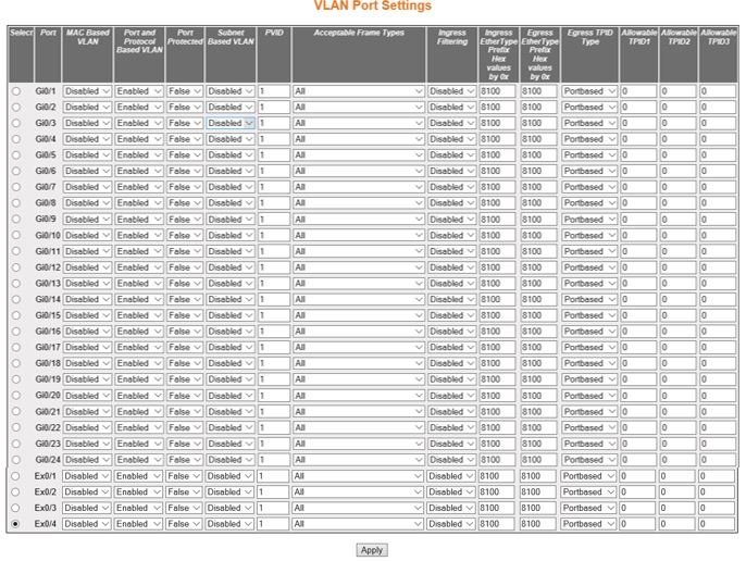
| Screen Objective | This screen allows the user to configure VLAN details such as VLAN membership classification
type for the physical ports available in the device. When all VLAN type related fields subnet
based on all ports, MAC- based
on all ports, and port and protocol based on all ports are set as
enabled, the VLAN membership classification is done in the following
order:
|
Note:
This screen is different for BCM target, refer the BCM specific screens chapter for more details. |
|
| Navigation |
|
| Fields |
|
| Fields |
|
| Fields (cont) |
|
| Fields (cont) |
|
| Buttons |
|
Static VLAN Configuration
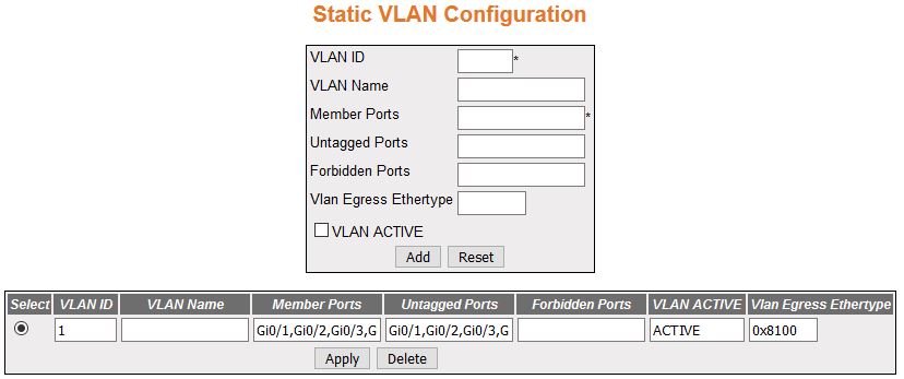
| Screen Objective | This screen allows the user to create / delete VLANs in the switch and statically configure
details such as member port for the VLANs
in the switch. These static configuration details are permanent
and can be restored after the switch is reset. Note:
The default VLAN entry, VLAN ID 1, cannot be deleted. |
| Navigation |
|
| Fields |
|
| Fields (cont) |
|
| Buttons |
|
VLAN Protocol Group Settings

| Screen Objective | This screen allows the user to create a protocol group with a specific protocol and encapsulation frame type combination. The created protocol group is used for protocol-VLAN based membership classification. The specified protocol is applied above the data-link layer in a protocol template, and the frame type is applied in the template. |
| Navigation |
|
| Fields |
|
| Fields (cont) |
|
| Fields (cont) |
|
| Buttons |
|
Port VLAN Protocol Settings
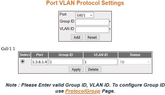
| Screen Objective | This screen allows the user to configure the VLANID set for a particular port for Port and Protocol Based VLAN classification. Only existing group ID can be assigned for the port. A VLAN ID which is not yet configured can be assigned for a port. When the VLAN is configured, forwarding will take place according to the VID set for the particular port. |
| Navigation |
|
| Fields |
|
| Buttons |
|
VLAN Port Mac Map
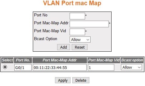
| Screen Objective | This screen allows the user to map the VLAN and MAC address for MAC-based VLAN classification. |
| Navigation |
|
| Fields |
|
| Fields (cont) |
|
| Buttons |
|
FDB Flush
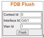
| Screen Objective | This screen allows the user to flush all dynamically generated MAC addresses. |
Note:
The output for FDB (File Data Buffer) flush cannot be verified in Web UI as viewing FDB is not implemented there. This can be seen only in CLI. |
|
| Navigation |
|
| Fields |
|
| Buttons |
|