Serial Communication

Serial communication is used to exchange information between two hosts. The most used serial communication standards are RS-232, RS-422, and RS-485 and these are supported on the serial-card. An understanding of these communication standards is needed to ensure correct connectivity and application. Presented here is a summary of these standards and how they can be used on a physical level

Comparison of Serial Communication Standards

Table 1. Comparison of Serial Communication Standards
  RS-232 RS-422 RS-485
Cable Single ended Single ended multi-drop Multi-drop
Number of Devices

1 transmitter

1 receiver

1 transmitter

10 receivers

32 transmitters

32 receiver

Communication Mode Full duplex

Full duplex,

Half duplex

Full duplex,

Half duplex

Maximum Distance 50 feet at 19200 bps 4000 feet at 100 kbps 4000 feet at 100 kbps
Maximum Data Rate 1 Mbps 10 Mbps at 50 feet 10 Mbps at 50 feet

RS-232

RS-232 is a short range connection between a single host and a single device (such as a PC to a modem) or another host (such as a PC to another PC). The standard uses a single TX line, a single RX line, numerous modem handshaking lines and a ground line with the option of DB9 and DB25 connectors. A minimal 3-wire RS-232 connection consists only the TX, RX, and ground lines, but if flow control is required a minimal 5-wire RS-232 is used adding the CTS and RTS lines. The RS-232 standard has been commonly used in computer serial ports and is still widely used in industrial communication devices.

Figure 1. RS-232


RS-232 Connectivity

A subset of the RS-232 standard signals are available on a serial card, and they allow for most use cases. The signals available are TX, RX, RTS, and CTS and can be used in different combinations to achieve different results.
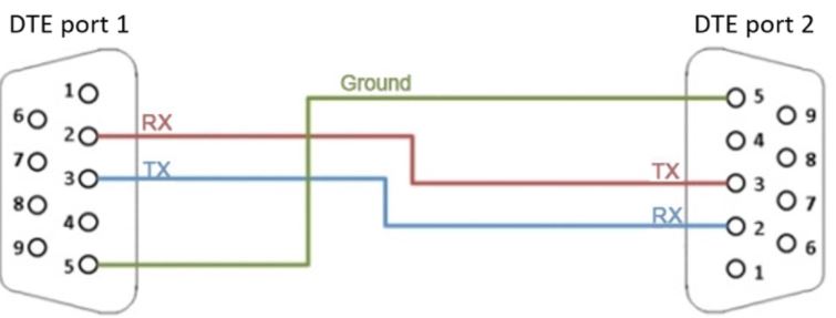
3-wire Mode

This is the simplest connection where two devices can communicate with each other which requires the use of the TX, RX, and ground lines. The TX line of one device is connected to the RX line of the other device (and visa versa). This allows one device to send a message to the other device and the other device to send a message back.

Figure 2. 3-wire Mode


Simple Null Modem Cable Route

In some cases, the communication takes place through another device, such as a modem. In this case, the RX and TX signals are not swapped.

Figure 3. Simple Null Modem Cable Route


Simple Straight Through Cable Route - 5-wire Mode

For the case where a device cannot process all the serial data at line speed, extra flow control signals can be used to pace the data into a device. This can be achieved with the RTS and CTS lines and are connected as follows:

Figure 4. Simple Straight Through Cable Route - 5 wire Mode


RS-422

RS-422 was meant as a replacement for RS-232 as it offered much higher speeds, better immunity to noise and allow for longer cable lengths making it better suited to industrial environments. The standard uses the same signals as the RS-232 standard, but used differential twisted pair so requires double the number of wires as RS-232. Connectors are not specified in the standard so block or DB connectors are commonly used. RS-422 cannot implement a true multi-point communications network since there can be only one driver on each pair of wires. However, one driver can fan-out to up to ten receivers.

Figure 5. RS-422


Direct Connect Mode

This is the equivalent of the RS-232 3-wire Mode for RS-422, but allows for faster speeds, longer cables as it is more immune to noise.

Figure 6. Direct Connect Mode


Multi Listener Mode

RS-422 also allows for up to 10 devices to be connected to the TX lines of the master. This allows for one-way communication (or only one device replying).

Figure 7. Multi Listener Mode


RS-485

The RS-485 standard addresses some short coming of the RS-422 standard. The standard supports inexpensive local networks and multidrop communication links, using the same differential signalling over twisted pairs as RS-422. The main difference being that in RS-485 drivers use three-state logic allowing the individual transmitters to deactivate while not transmitting, while RS-422 the transmitter is always active therefore holding the differential lines. Up to 32 devices can be connected, but with repeaters a network with up to 256 devices can be achieved. RS-485 can be used in a full-duplex 4-wire mode or half-duplex 2-wire mode. With long wires and high baud-rates it is recommended that termination resistors are used at the far ends of the network for signal integrity.

Figure 8. RS-485


4-Wire Full-duplex Mode

In 4-wire mode, the master, which can be either RS-485 or RS-422, can transmit a message to all RS-485 slaves and the addressed slave can reply to the master. Slaves can not communicate among themselves.

Figure 9. 4-wire Full-duplex Mode


2-wire Half-duplex Mode

In this mode all devices can communicate with each other, but only one device can communicate at a time. Higher level protocols and addressing schemes need to be used.

Figure 10. 2-wire Half-duplex Mode