This section describes the Routing Information Protocol
(RIP) on the switch.
RIP (Routing Information
Protocol) is a widely-used protocol for managing router information
within a self-contained network such as a corporate local area network
or an interconnected group of such LANs.
RIP sends routing-update messages
at regular intervals and when the network topology changes. When a
router receives a routing update that includes changes to an entry,
it updates its routing table to reflect the new route. The metric
value for the path is increased by 1, and the sender is indicated
as the next hop. RIP routers maintain
only the best route (the route with the lowest metric value) to
a destination. After updating its routing table, the router immediately
begins transmitting routing updates to inform other network routers
about the change. These updates are sent independently of the regularly
scheduled updates that RIP routers
send. RIP uses a hop count as
a way to determine network distance. Each host with a router in
the network uses the routing table information to determine the
next host to route a packet for a specified destination.
To access RIP screens, go to .
RIP VRF Creation
By
default, the tab Basic Settings displays
the DHCP Relay Configuration screen.
Figure 1. RIP VRF Creation

| Screen Objective |
This screen allows the user to enable or disable RIP for default VRF (Virtual Routing and Forwarding)
instance. |
| Navigation |
|
| Fields |
- VRF Name—default
is available for a VRF context
name for which RIP has to be enabled or disabled. VRF allows multiple instances of
a routing table to co-exist within the same router at the same time.
- VRF Status—select the VRF status in the router. The default
option is Disabled. The list contains:
- Disabled—disables RIP on the VRF instance.
- Enabled—enables RIP on the VRF instance to allow multiple instances
of a routing table
|
| Buttons |
- Add—adds and
saves new configuration.
- Delete—deletes the selected entry.
|
RIP Basic Settings
Figure 2. RIP Basic Settings
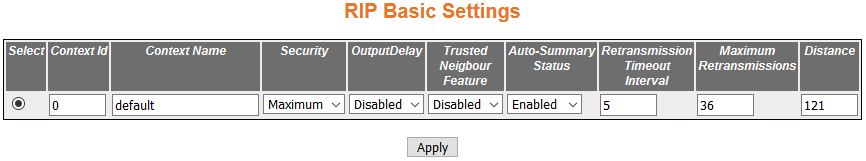
| Screen Objective |
This screen allows the user to configure the
basic settings of RIP. |
| Navigation |
|
| Fields |
- Select—click
to select the Context ID for which the RIP configuration
is modified.
- Context ID—default.
- Context Name—displays the Context name
for the VRF instance. This value represents
unique name of the VRF instance
and is a string of maximum sizeof 32.
- Security—select the security level of RIP to accept / ignore RIPv1 packets when authentication
is in use. The default option is Maximum. The list contains:
- Minimum—sets
the security status for the RIP domain
context as minimum. When minimum security is set, the RIP packets will be accepted even
when authentication is in use.
- Maximum—sets the security status for the RIP domain
context as maximum. When maximum security is set, RIP packets will be ignored when
authentication is in use.
|
| Fields (cont) |
- OutputDelay—select
Output Delay status for the RIP Domain
Context. The default option is Disabled. The list contains:
- Enabled—sets
Output Delay status as Enabled and enables interpacket delay for
RIP updates, where the delay between packets in a multiple-packet
RIP update is in milliseconds. This interpacket delay feature helps
in preventing the routing table from losing information due to flow
of RIP update from high speed
router to low speed router.
- Disabled—sets Output delay status in the RIP Domain
context as Disabled; thereby, disabling interpacket delay for RIP packets.
- Trusted Neighbour Feature—select Trusted
Neighbour Feature for the RIP domain context. The default option
is Enabled. The list contains:
- Enabled—sets the Trusted Neighbour
Feature status as Enabled. When Enabled, a list of routers’ IP addresses
can be configured. RIP Packets
from those routers will be processed by RIP,
and packets from other routers will be dropped.
- Disabled—sets the Trusted Neighbour Feature status as Disabled.
When Disabled, RIP Packets from
all routers will be processed.
- Auto-Summary Status—select the Auto Summary
status for the RIP domain context.
The default option is Enabled. The list contains:
- Enabled—sets
the Auto Summary Status for the RIP domain
context as Enabled. When Enabled, summary routes are sent in regular
updates for both RIP version 1
and version 2. The summary is sent only if at least one subnet route,
which is different from the interface over which the update is sent,
is learned over an interface.
- Disabled—sets the Auto Summary Status for the RIP domain context as Disabled.
When Disabled, either individual subnet route is sent, or subnet routes
are sent based on the specific aggregation configured over the interface.
- Retransmission Timeout Interval—enter
the timeout interval to be used to retransmit the update request
packet or an unacknowledged update response packet. The packets
are transmitted at the specified interval till a response is received
or the maximum number of retries is reached. The value ranges from
5 to 10. The default value is 5.
- Maximum Retransmitions—enter the maximum
number of retransmissions of the update request and update response
packets. If no response is received. the routes via the next hop
router are marked unreachable. This value ranges from 10 to 40 seconds.
The default value is 36.
- Distance—enter the distance value for
the specified context id. This value ranges from 1 to 255. The default
value is 121.
|
| Buttons |
- Apply—modifies
attributes and saves the changes.
|
RIP Interface
Figure 3. RIP Interface
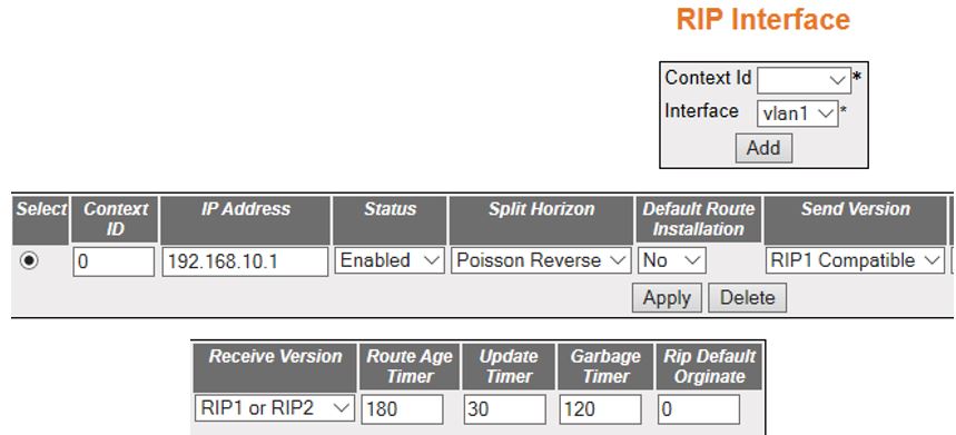
| Screen Objective |
This screen allows the user to configure RIP on the specified interface. |
| Navigation |
|
| Fields |
- Select—click
to select the Context ID for which the configuration needs to be modified
or deleted.
- Context ID—default.
- Interface—select the interface ID for
which the RIP parameters need
to be configured.
Note: The VLAN interface
can be created in Layer 2 Management->VLAN screen
- IP Address—displays the IP Address of
the RIP interface. This is a read-only
field.
- Status—select the administrative status
of the RIP2 in the router. The
default option is Enabled. The list contains:
- Enabled—activates RIP2 process throughout the system.
- Disabled—disables RIP2 process
in the system.
- Passive—runs RIP2 process
as a passive one.
- Split Horizon—select the operational
status of split horizon in the system. The default option is Poison
Reverse. The list contains:
- Split Horizon—enables the Split
Horizon updates for the RIP which
prevents the routing loops in distance routing protocol. This is
done by prohibiting the router from advertising a route back onto
the interface. The Split Horizon updates are applied in the response
packets sent.
|
| Fields (cont) |
- Split Horizon—the
list contains (cont):
- Poisson Reverse—enables the poison
updates for the RIP which sends
route with the metric value 16 on an interface from which route
is learnt.
- Disabled—disables Split Horizon updates for the RIP which sends route on all interfaces
with the metric same as that in the RIP Routing
Table.
- Default Route Installation—select the
default route installation status in the RIP Interface.
The default option is No. The list contains:
- Yes—enables
default route installation which installs the default route received
in updates to the RIP database.
- No—disables default route installation which blocks the installation
of default route received in updates to the RIP database.
- Send Version—select the version of RIP packets that will be sent by
the router. The default option is RIP1
Compatible. The list contains:
- Do not send—stops the IP RIP transmitting advertisements
to be sent on a VLAN interface / router port
- RIP Version1 sends only RIP updates compliant with RFC 1058.
- RIP1 Compatible—sends both
Multicasting RIP updates and RIP updates compliant with RFC 1058
on the interface.
- RIP Version2—sends only Multicasting RIP updates on the interface
- Receive Version—select the version of RIP updates to be received. The
default option is RIP1 or RIP2. The list contains:
- RIP1—receives only RIP updates compliant with RFC 1058
on the interface.
- RIP2—receives only multicasting RIP updates on the interface.
- RIP1 or RIP2—receives
both multicasting RIP updates
and RIP updates compliant with
RFC 1058 on the interface.
- Do not receive—sets that no IP RIP transmitting
advertisements are received on a VLAN interface
/ router port.
- Route Age Timer—enter the time (in sec)
after which the route entry goes in garbage collect (marked as invalid).
The value is from 30 to 500 sec—default 180.
- Update Timer—enter the time interval
(in seconds) at which the RIP updates should
be sent. This is the fundamental timing parameter of the routing
protocol. The value ranges from 10 to 3600 seconds. The default
value is 30.
- Garbage Timer—enter the time (in seconds)
after which the route entry marked as invalid is deleted. The advertisement
of this entry is set to INFINITY while sending to others. The value
ranges from 120 to 180 seconds with a default of 120.
- Rip Default Originate—enter the metric
to be used for default route propagated over the VLAN interface
/ router port in a RIP update
message and generates a default route into RIP. This value ranges
from 0 to 15. The default option is 0 which implies that origination
of default route over the interface is disabled.
|
| Buttons |
- Apply—modifies
attributes and saves the changes.
|
RIP Neighbour List
Figure 4. RIP Neighbour List
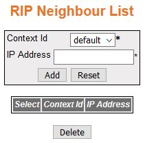
| Screen Objective |
This screen allows the user to add a trusted
neighbor router with which routing information can be exchanged
and from which RIP packets can
be accepted. This permits the point-to-point (non broadcast) exchange
of routing information. When used in combination with the passive-interface VLAN, routing information can be exchanged
between a subset of routers and access servers. On a LAN, multiple neighbor
IP addresses can be used to specify additional neighbors or peers. |
| Navigation |
|
| Fields |
- Select—click
to select the Context ID for which the configuration needs to be modified
or deleted.
- Context ID—default.
- IP Address—enter the IP Address of the
neighbor router from which this router will accept RIP packets
|
| Buttons |
- Add—adds and
saves new configuration.
- Reset—resets to default value for respective
fields and discards all user input.
- Delete—deletes the selected entry.
|
RIP Security Settings
Figure 5. RIP Security Settings
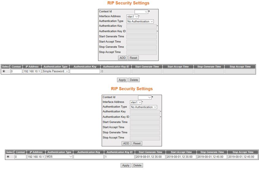
| Screen Objective |
This screen allows the user to configure the
type of authentication that is used on the interface. |
| Navigation |
|
| Fields |
- Select—click
to select the Context ID for which the configuration needs to be modified
or deleted.
- Context ID—default.
- Interface Address—select the required
interface from the list of interfaces for which crypto authentication
parameters are to be configured.
Note: The VLAN interface can be created in
Layer 2 Management->VLAN screen
|
| Fields (cont) |
|
| Fields (cont) |
|
| Buttons |
- Create—adds
and saves new configuration.
- Reset—resets to default value for respective
fields and discards all user input.
- Apply—modifies attributes and saves the
changes.
- Delete—deletes the selected entry.
|
RIP Interface Specific Address Summarization
Figure 6. RIP
Interface Specific Address Summarization
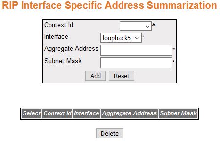
| Screen Objective |
This screen allows the user to set route aggregation
over a VLAN interface / router
port for all subnet routes that fall under the specified IP address
and mask. |
| Navigation |
|
| Fields |
- Select—click
to select the Context ID for which summary address is to be deleted.
- Context ID—default.
- Interface—select the Interface ID from
the list of VLAN interfaces created
in the system to configure the summary address.
- Aggregate Address—enter the IP Address
that is to be combined with the subnet mask to set route aggregation
for all subnet routes that fall under the specified IP address and
mask of the interface specific aggregation.
- Subnet Mask—enter the subnet mask that
is to be combined with the IP address to set route aggregation for
all subnet routes that fall under the specified mask and IP address
of the interface specific aggregation.
|
| Buttons |
- Add—adds and
saves new configuration.
- Reset—resets to default value for respective
fields and discards all user input.
- Delete—deletes the selected entry.
|