Describes the QoS Ingress
settings.
QoS (Quality of Service)
defines the ability to provide different priorities to different
applications, users, or data flows or the ability to guarantee a
certain level of performance to a data flow. QoS refers
to resource reservation control mechanisms rather than the achieved
service quality and specifies a guaranteed throughput level.
The QoS module provides a complete
IP QoS solution across VPNs and
helps in implementing service provisioning policies for application
or customers, who desire to have an enhanced performance for their traffic
on the Internet.
QoS Ingress refers to the quality
of service offered to the incoming packets.
To access QoS Ingress screens, go to .
Basic Settings
By
default, the tab Basic Settings displays
the Basic Settings screen.
Figure 1. QoS
Basic Settings
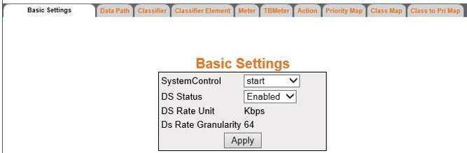
| Screen Objective |
This screen allows the user to configure the
basic settings of QoS. |
| Navigation |
|
| Fields |
- System Control—select
the control type of the QoS module
in the system. The default option is start. The list contains:
- start—starts QoS in the system. Resources required
by QoS module are allocated and
the QoS module starts running.
- shutdown—shuts down QoS in
the system. All pools used by QoS module
are released to the system.
- DS Status—select the status of the QoS module in the system. The default
option is Enabled. The list contains.
- Enabled—enables QoS Module. The QoS module programs the hardware
and starts protocol operation.
- Disabled—disables QoS Module.
This stops protocol operation by deleting the hardware configuration
Note: DS
Status can be enabled only if QoS is
started in the system.
- DS Rate Unit—displays the unit for the
information rate values based on target platform. The default value
is Kbps. The rate unit can be any one of the following:
- bps—bits
per second.
- Kbps—Kilobits per second
- mbps—megabits per second
- gbps—gigabits per second
- DS Rate Granularity—displays the acceptable
granularity level for configuring the information rate (CIR, EIR,
PIR, PTR, and CTR) values for a target platform. The default value
is 64.
|
| Buttons |
- Apply—modifies
attributes and saves the changes.
|
Data Path
Figure 2. Data
Path
| Screen Objective |
This screen allows the user to configure the
data path settings. The Data Path table enumerates
the differentiated services functional data paths within the device. |
Note: - This screen can
be configured only if QoS is started
in the system using the Basic Settings screen.
- The entries in the bottom form are displayed only if QoS is started in the system.
|
| Navigation |
|
| Fields |
|
| Buttons |
- Add—adds and
saves new configuration.
- Modify—modifies attributes and saves
the changes.
- Reset—resets to default value for respective
fields and discards all user inputs.
- Delete—deletes the selected entry.
|
Classifier
Figure 3. Classifier
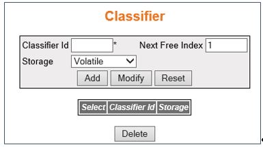
| Screen Objective |
This screen allows the user to configure the
classifier settings. Packet classifiers select packets in a traffic
stream based on the content of some portion of the packet header. Classifiers
are used to steer packets matching some specified rule to an element
of a traffic conditioner for further processing. |
Note: - This screen can
be configured only if QoS is started
in the system using the Basic Settings screen.
|
| Navigation |
|
| Fields |
- Classifier Id—enter
the index that enumerates the classifier entries. This value ranges
from 1 to 65535.
- Next Free Index—displays an integer which
may be used as a new index in the table. The value of zero indicates
that no more new entries can be created in the relevant table. This
is a read only field.
- Storage—select the storage type for the
conceptual row. The default option is Volatile. Options are:
- Volatile—reflects
the configurations for an interface whose interface index has been
assigned, and for which the supporting implementation is currently present.
- Non-Volatile—reflects the configuration for an interface whose
interface index has been assigned but for which the supporting implementation
is currently not present
|
| Buttons |
- Add—adds and
saves new configuration
- Modify—modifies attributes and saves
the changes
- Reset—resets to default value for respective
fields and discards all user inputs
- Delete—deletes the selected entry.
|
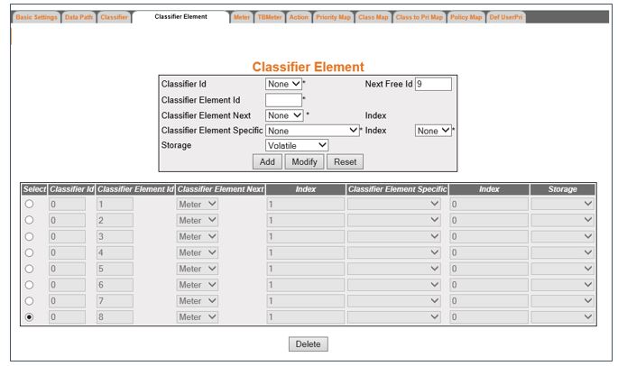
Classifier Element
Figure 4. Classifier Element
| Screen Objective |
This screen allows the user to configure the Classifier
Element settings. All traffic presented to a classifier
must match at least one classifier element within the classifier,
with the classifier element parameters specified by a filter. The
classifier element table enumerates the relationship between classification
patterns and subsequent downstream Differentiated Services Functional
Data Path elements. |
Note: - This screen can
be configured only if QoS is started
in the system using the Basic Settings screen.
|
| Navigation |
|
| Fields |
|
| Fields (cont) |
|
| Buttons |
- Add—adds and
saves new configuration.
- Modify—modifies attributes and saves
the changes.
- Reset—resets to default value for respective
fields and discards all user inputs.
- Delete—deletes the selected entry.
|
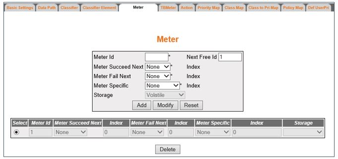
Meter
Figure 5. Meter
| Screen Objective |
This screen allows the user to configure the
meter settings. Meters are used to police a stream of traffic. The
traffic stream to be metered is determined by the Differentiated Services
Functional Data Path Element(s) upstream of the meter. |
Note: - This screen can
be configured only if QoS is started
in the system using the Basic Settings screen.
|
| Navigation |
|
| Fields |
|
| Fields (cont) |
|
| Buttons |
- Add—adds and
saves new configuration
- Modify—modifies attributes and saves
the changes
- Reset—resets to default value for respective
fields and discards all user inputs
- Delete—deletes the selected entry.
|
Token Bucket Meter
Figure 6. Token Bucket Meter
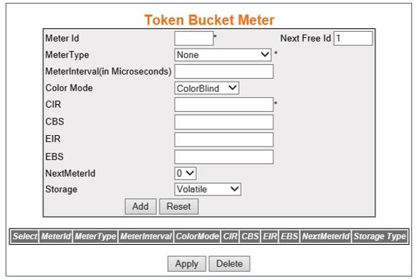
| Screen Objective |
This screen allows the user to configure the
token bucket parameters. Each entry in the Token Bucket (TB) Parameter Table is used to configure
a single token bucket. Multiple token buckets can be used together
to parameterize multiple levels of conformance. |
Note: - This screen can
be configured only if QoS is started
in the system using the Basic Settings screen.
|
| Navigation |
|
| Fields |
- Meter Id—select
the index that enumerates the TB meter
entries. This value ranges from 1 to 65535.
- Next Free Id—displays an integer which
may be used as a new index in the table. The value of zero indicates
that no more new entries can be created in the relevant table. This
is a read only field.
|
| Fields (cont) |
- Meter Type—select
the metering algorithm associated with the token bucket parameters.
Options are:
- None—does not sets any metering algorithm associated
with the token bucket parameters.
- simpleTokenBucket—sets the meter type as Two Parameter Token
Bucket Meter.
Note: When this option is selected, MeterInterval, EIR, and EBS are
greyed out.
- avgRate—sets the meter type as Average Rate Meter. It supports
interval and committed information rate (CIR)
parameters.
Note: When this option is selected, CBS, EIR,
and EBS are greyed out.
- srTCM—sets the meter type as Single Rate Three Color Marker
Metering as defined by RFC 2697. It supports CIR,
committed burst size (CBS) and
excess burst size (EBS) parameters.
Note: When
this option is selected, MeterInterval and EIR are
greyed out.
- trTCM—sets the meter type as Two Rate Three Color Marker Metering
as defined by RFC 2698. It supports CIR, CBS, excess information rate (EIR), and excess burst size (EBS) parameters.
Note: When this
option is selected, MeterInterval is greyed out.
- tswTCM—sets the meter type as Time Sliding Window Three Color
Marker Metering as defined by RFC 2859.
Note: When this option
is selected, CBS and EBS are greyed out.
- mefDecoupleMeter—sets the meter type as Dual bucket meter as
defined by RFC 4115.
Note: When this option is selected, MeterInterval
is greyed out.
- mefCoupledMeter—sets the meter type as Dual bucket meter as
defined by RFC 2697 and MEF coupling Flag.
Note: When this option
is selected, MeterInterval and EIR are
greyed out.
- MeterInterval(in Microseconds)—enter
the time interval used with the token bucket. This value ranges
from 1 to 10000 microseconds.
Note: Meter Interval is mandatory
if the Meter Type is set as avgRate and tswTCM. This field is greyed
out for all other meter types.
- Color Mode—select the color mode of the
meter. The default option is ColorBlind. Options are:
- ColorBlind—sets
the meter to ignore the pre-color of the packet.
- ColorAware—sets the meter to consider the pre-color of the packet.
|
| |
- CIR—enter the
Committed Information Rate (CIR).
It defines the average rate in bits/s of Service Frames up to which
the network delivers Service Frames and is committed to meeting
the performance objectives defined by the CoS Service Attribute.
This value ranges from 0 to 65535. The default value is 0.
Note: CIR
must be less than or equal to EIR if EIR is greater than 0.
Note: This
configuration is applicable for all meter type.
- CBS—enter the committed burst size (CBS). This value ranges from 0 to
65535. The default value is 0.
Note: CBS must
be greater than 0 if CIR is greater
than 0.
Note: This configuration is not applicable if
meter type is avgRate and tswTCM.
- EIR—enter the excess information rate
(EIR). This value ranges from
0 to 65535. The default value is 0.
Note: EIR must
be greater than or equal to CIR if EIR is
greater than 0.
Note: This configuration is not applicable
if meter type is simpleTokenBucket, avgRate, srTCM, and mefCoupledMeter.
- EBS—enter the excess burst size (EBS). This value ranges from 0 to
65535. The default value is 0.
Note: EBS must
be greater than 0 if EIR is greater
than 0.
Note: This configuration is not applicable if
meter type is simpleTokenBucket, avgRate, and tswTCM.
- NextMeterId—select the meter entry ID
to be used for applying the second/next level of conformance on
the incoming packet. The default value is 0.
- Storage—select the storage type for the
conceptual row. The default option is Volatile. Options are:
- Volatile—reflects
the configurations for an interface whose interface index has been
assigned, and for which the supporting implementation is currently present.
- Non-Volatile—reflects the configuration for an interface whose
interface index has been assigned but for which the supporting implementation
is currently not present.
|
| Buttons |
- Add—adds and
saves new configuration.
- Reset—resets to default value for respective
fields and discards all user inputs.
- Apply—modifies attributes and saves the
changes.
Note: The attributes cannot be modified for the meter
id which is set as a Next Meter ID by another entry.
- Delete—deletes the selected entry.
Note: The
meter Id which is set as the Next Meter Id by another entry cannot
be deleted. To delete this Meter ID, the Meter ID which uses this
ID as its Next Meter ID should be deleted first.
Note: For
example, if the Meter ID 2 is set as the Next Meter ID for the Meter
ID 6, the Meter ID 6 should be deleted first, and then only Meter
ID 2 can be deleted.
|
Action
Figure 7. Action

| Screen Objective |
This screen allows the user to configure the
action settings. The Action table allows enumeration
of the different types of actions to be applied to a traffic flow. |
Note: - This screen can
be configured only if QoS is started
in the system using the Basic Settings screen.
|
| Navigation |
|
| Fields |
- Action Id—enter
the index that enumerates the action entries. This value ranges from
1 to 65535.
- Next Free Id—displays an integer which
may be used as a new index in the table. The value of zero indicates
that no more new entries can be created in the relevant table. This
is a read only field.
|
| Fields (cont) |
- Interface—specifies
the interface index where action occurs.
- Action Next—select the next differentiated
services functional data path element to handle traffic for this
data path. Options are:
- None—disables the action to be performed.
- AlgoDrop—enables the algorithm drop action.
- Queue—enables queue setting action.
- Index—specifies the available entries
of corresponding functional blocks displayed by Action Next.
- Action Specific—select the pointer to
an object instance providing additional information for the type
of action indicated by this action table entry. Options are:
- None—disables
the pointer to an object instance providing additional information.
- Dscp Mark Act Entry—enables the pointer to an object instance
providing description for action table entry.
- Count Act Entry—enables the pointer to an object instance providing
count for action table entry.
- AlgoDrop—enables Drop Algorithm for Congestion Management.
- Index—specifies the available entries
of corresponding functional blocks displayed by Action Specific.
- Storage—select the storage type for the
conceptual row. The default option is Volatile. Options are:
- Volatile—reflects
the configurations for an interface whose interface index has been
assigned, and for which the supporting implementation is currently present.
- Non-Volatile—reflects the configuration for an interface whose
interface index has been assigned but for which the supporting implementation
is currently not present.
|
| Buttons |
- Add—adds and
saves new configuration.
- Modify—modifies attributes and saves
the changes.
- Reset—resets to default value for respective
fields and discards all user inputs.
- Delete—deletes the selected entry.
|
Priority Map Settings
Figure 8. Priority Map Settings

| Screen Objective |
This screen allows the user to configure the Priority
Map settings. The Priority Map table
is used to map incoming priority to a regenerated priority. This
table is used to regenerate port / VLAN priorities
for an incoming packet. It can be used to directly program priority
tables in the hardware. |
Note: - This screen can
be configured only if QoS is started
in the system using the Basic Settings screen.
|
| Navigation |
|
| Fields |
- PriorityMap Id—enter
a unique ID for priority map. This represents the output priority
map index for the incoming packet received over ingress PORT/ VLAN with specified incoming priority.
This value ranges from 1 to 65535.
Note: The default priority
maps with the IDs 1 to 8 are already created in the system and cannot
be deleted.
|
| Fields (cont) |
- Ingress Interface—select
the incoming port number from the list of interfaces created in
the system.
- VLAN ID—enter the VLAN identifier
for priority regeneration. The default value is 0. This value ranges
from 1 to 4094.
- In Priority—enter the incoming priority
value determined for the received frame. This value is equivalent
to the priority (VLAN (4 bit)/DSCP
(6 bit) priority bits) indicated in the received frame or one of
the evaluated priorities. This value ranges from 0 to 63. The default
value is 0.
- PriType—select the incoming priority
type used to identify the incoming priority. The default option
is VlanPri. Options are:
- VlanPri—sets the incoming priority
type as VLAN.
- IpTos—sets the incoming priority type as IP Type of Service.
- IpDscp—sets the incoming priority type as IP Differentiated
Services Code Point.
- MplsExp—sets the incoming priority type as MPLS Experimental.
- Regen Priority—enter the regenerated
priority value determined for the received frame. This value ranges
from 0 to 63. The default value is 0.
- Regen Inner Priority—enter the regenerated
inner-vlan (CVLAN) priority
value determined for the received frame. This value ranges from
0 to 8.
|
| Buttons |
- Add—adds and
saves new configuration.
- Reset—resets to default value for respective
fields and discards all user inputs.
- Apply—modifies attributes and saves the
changes.
Note: The attributes of auto generated default Priority
Maps (1–8) cannot be modified.
- Delete—deletes the selected entry.
Note: Auto
generated default Class Maps (1–8) cannot be deleted
|
Class Map Settings
Figure 9. ClassMap Settings
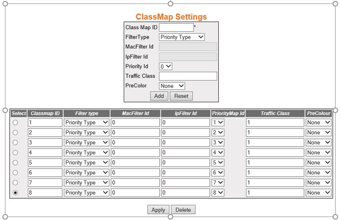
| Screen Objective |
This screen allows the user to classify the
stream of traffic. The class map table takes input from the ACL or priority-map table and outputs
a Class for the traffic-class pattern/match. |
Note: - This screen can
be configured only if QoS is started
in the system using the Basic Settings screen.
|
| Navigation |
|
| Fields |
- Class Map Id—enter
a unique ID for every classmap. This value ranges from 1 to 65535.
Note: The
auto generated default class with the IDs 1 to 8 are already created
in the system and cannot be deleted.
- FilterType—select the filter type associated
with every classmap. The default option is Priority Type. Options
are:
- Priority Type—set the filter type associated with the
Classmap as priority type.
- MAC or IP type—set the filter
type associated with the Classmap as MAC or IP
type.
|
| Fields (cont) |
- MacFilter Id—enter
the MAC filter ID (L2 Filter Id)
associated with this classmap. This value ranges from 0 to 65535.
The default value is 0.
Note: This field can be configured only
if Filter Type is set as MAC or
IP Type.
- IpFilter Id—enter the IP filter ID (L3
Filter Id) associated with this classmap. This value ranges from
0 to 65535. The default value is 0.
Note: This field can be configured
only if Filter Type is set as MAC or
IP Type.
- Priority Id—select the Priority Map ID
for mapping incoming priority against the received packets. The
default value is 0.
Note: This field lists the priority map ids
created using the Priority Map Settings screen.
Note: Priority
ID can be associated with the classmap only if Filter Type is set
as Priority Type.
- Traffic Class—enter the traffic class
associated with the classmap. This value ranges from 0 to 65535.
The default value is 0.
- PreColor—select the color of the packet
prior to metering. The default Drop-precedence for the packet can
be evaluated using the color assigned to the packet. The default
option is None. Options are:
- None—sets the color of the packets
to None. This implies that traffic is not pre-colored.
- Green—sets the color of the packets to None. This implies that
traffic conforms to service-level agreements (SLA)s.
- Yellow—sets the color of the packets to None. This implies that
traffic exceeds the SLAs.
- Red—sets the color of the packets to None. This implies that
traffic violates the SLAs.
|
| Buttons |
- Add—adds and
saves new configuration.
- Reset—resets to default value for respective
fields and discards all user inputs.
- Apply—modifies attributes and saves the
changes.
- Delete—deletes the selected entry.
Note: Auto
generated default Class Maps (1–8) cannot be deleted.
|
Class to Priority Settings
Figure 10. ClasstoPri Settings

| Screen Objective |
This screen allows the user to configure the
class to priority settings. The ClassToPriority table assigns local
priority values for an input Class. This table provides easy mapping
of Class to priority values. |
Note: - This screen can
be configured only if QoS is started
in the system using the Basic Settings screen.
|
| Navigation |
|
| Fields |
- Class—select
the traffic class to which an incoming frame pattern is classified.
This value ranges from 1 to 2147483647.
Note: This field lists
the traffic class IDs created using the ClassMap Settings screen.
- RegenPri—enter the regenerated priority
value determined for the input class. This value ranges from 0 to
7.
- GroupName—enter the unique identification
of the group to which an input class belongs. This value is a string
of size from 1 to 31.
|
| Buttons |
- Add—adds and
saves new configuration.
- Reset—resets to default value for respective
fields and discards all user inputs.
- Apply—modifies attributes and saves the
changes.
- Delete—deletes the selected entry.
|
Policy Map Settings
Figure 11. PolicyMap Settings

| Screen Objective |
This screen allows the user to configure action
for a specified Class Map. This allows the user to map a policy
for a classmap. |
Note: - This screen can
be configured only if QoS is started
in the system using the Basic Settings screen.
|
| Navigation |
|
| Fields |
- Policy Map ID—enter
the unique ID for policy map. This value ranges from 1 to 65535.
Note: The
auto generated default policy map with the Id of 1 cannot be deleted.
|
| Fields (cont) |
- Ingress Interface—select
the incoming port number from the list of ports available in the
system.
- Traffic Class—Select the traffic class
for which the policy map needs to be applied.
Note: This field
lists the Traffic class IDs created using the Class Map Settings screen.
- PHB Type—select the PHB (Per Hop Behavior) type to be
used for filling the default PHB for the policy map entry. Options
are:
- None—disables the PHB type
for the policy map entry.
- VlanPri—enables VLAN priority
type for the policy map entry.
- ipTos—enables IP Type of Service type for the policy map entry.
- ipDscp—enables as IP DSCP for
the policy map entry.
- mplsExp—enables MPLS Experimental
for the policy map entry.
- DefaultPHB Value—enter the default outgoing PHB values for the policy map. This value
ranges from 0 to 63.
- Meter Id—select a meter table ID which
is the index for the meter table from the list of meters configured
in the system. The default value is 0:
- Conform Act—enter the default outgoing PHB values for the policy map. This value
ranges from 0 to 63.
- None—disables action to be performed
on the packet
- ActionIPsetPort—sets the new port value.
- ConformActionIPTos—sets the new IP TOS value.
- ConformActionDSCP—sets the new DSCP value.
- ConformActionVlanPriandDE—sets the VLAN priority
and VLAN Drop Eligible indicator
of the outgoing packet.
- ConformActionInnerVlanPri—sets the Inner VLAN priority
of the outgoing packet.
- ConformActionMplsEXP—sets the MPLS Experimental
bits of the outgoing packet.
- ConAct Value 1—enter the conform action
value for either VlanPri or VlanDe. The value ranges from 0 to 7.
The default value is 0.
Note: This field is greyed out and cannot
be configured if the Conform Act is set as None.
- ConAct Value 2—enter the conform action
value for either VlanPri or VlanDe. The value ranges from 0 to 7.
The default value is 0.
Note: This field is greyed out and cannot
be configured if the Conform Act is set as None, ActionIPsetPort,
ConformActionIPTos and ConformActionClanPriandDE.
|
| Fields (cont) |
- ConAct NEWCLASS1—enter
the traffic class to which an incoming frame pattern is classified
after metering. The priority of the New CLASS should be lower as compared
to the CLASS assigned prior to metering. The value ranges from 0
to 65535. The default value is 0.
Note: This field is greyed out
and cannot be configured if the Conform Act is set as None.
- Exceed Action—select the action to be
performed on the packet, when the packets are found to be in profile.
The default option is None. Options are:
- None— disables actions
to be performed on the packet
- Drop—drops the packet.
- ExceedActionIPTos—sets the new IP TOS value.
- ExceedActionDSCP—sets the new DSCP value.
- ExceedActionVlanPriandDE—sets the VLAN priority
and VLAN Drop Eligible indicator
of the outgoing packet.
- ExceedActionInnerVlanPri—sets the Inner VLAN priority
of the outgoing packet.
- ExceedActionMplsEXP—sets the MPLS Experimental
bits of the outgoing packet.
- ExcAct Value 1—specifies the exceed action
value for either VlanPri or VlanDe. This value ranges from 0 to
7. The default value is 0.
Note: This field is greyed out and
cannot be configured if the Exceed Action is set as None or Drop.
- ExcAct Value 2—specifies the exceed action
value for either VlanPri or VlanDe. This value ranges from 0 to
7. The default value is 0.
Note: This field is greyed out and
cannot be configured if the Exceed Action is set as None, Drop,
ExceedActionIpTos, or ExceedActionDSCP.
- ConAct NEWCLASS1—enter the traffic class
to which an incoming frame pattern is classified after metering.
The priority of the New CLASS should be lower as compared to the
CLASS assigned prior to metering. The value ranges from 0 to 65535.
The default value is 0.
Note: This field is greyed out and cannot
be configured if the Exceed Action is set as None or Drop.
|
| Fields (cont) |
- Violate Act—specifies
the exceed action value for either VlanPri or VlanDe. This value
ranges from 0 to 7. The default value is 0.
- None—disables
action to be performed on the packet
- Drop—drops the packet.
- ViolateActionIPTos—sets the new IP TOS value.
- ViolateActionDSCP—sets the new DSCP value.
- ViolateActionVlanPriandDE—Sets the VLAN priority
and VLAN Drop Eligible indicator
of the outgoing packet.
- ViolateActionInnerVlanPri—sets the Inner VLAN priority
of the outgoing packet.
- ViolateActionMplsEXP—sets the MPLS Experimental
bits of the outgoing packet
- Violate Value1—specifies the violate
action value for either VlanPri or VlanDe. The value ranges from
0 to 7. The default value is 0. The default value is 0.
Note: This
field is greyed out and cannot be configured if the Violate Act
is set as None or Drop.
- Violate Value2—specifies the violate
action value for either VlanPri or VlanDe. The value ranges from
0 to 7. The default value is 0. The default value is 0.
Note: This
field is greyed out and cannot be configured if the Exceed Action
is set as None, Drop, ExceedActionIpTos, or ExceedActionDSCP.
- VioActNEWCLASS —represents the traffic
class to which an incoming frame pattern is classified after metering.
The priority of the New CLASS should be lower as compared to the
CLASS assigned prior to metering. The value ranges from 0 to 65535.
The default value is 0.
Note: This field is greyed out and cannot
be configured if the Violate Act is set as None or Drop.
|
| Buttons |
- Add—adds and
saves new configuration.
- Reset—resets to default value for respective
fields and discards all user inputs.
- Apply—modifies attributes and saves the
changes.
- Delete—deletes the selected entry.
Note: This
field is greyed out and cannot be configured if the Violate Act
is set as None or Drop.
|
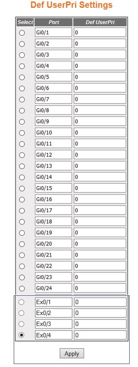
Def UserPri Settings
Figure 12. Def UserPri Settings
| Screen Objective |
This screen allows the user to configure the
default user priority settings. The default user priority is used
to assign ports to the untagged packets and to specify preference for
p-bit over DSCP in tagged packets. |
Note: - This screen can
be configured only if QoS is started
in the system using the Basic Settings screen.
- The entries are displayed only if QoS is
started in the system.
|
| Navigation |
|
| Fields |
- Port—specifies
the port, which is a combination of interface type and interface
ID. The interface ID is a combination of slot number and the port
number (slot number/port number
- Def UserPri—enter the default ingress
user priority for the specified port. The default value is 0. This
value ranges from 0 to 7.
|
| Buttons |
- Apply—modifies
attributes and saves the changes.
|