HSR/PRP

The HSR/PRP configuration and status web pages are as shown below.

To access HSR/PRP screens, go to Layer 2 Management > HSR/PRP.

HSR/PRP Interface Configuration and Status

Figure 1. HSR/PRP Interface Configuration and Status
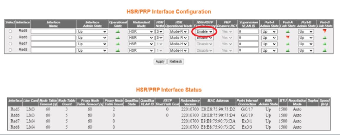

Screen Objective This screen allows the user to configure the HSR/PRP Interface Configuration.
Navigation

Layer 2 Management > HSR/PRP > Configuration Status

Fields
  • Select—select the index to modify the attributes.
  • Interface—this is a status field that shows the redundant interface.
  • Interface Name—enter an interface name. It is an optional field. The maximum length is 64 characters.
  • Interface Admin State—select an admin state from the drop-down list. If you select Bypass (Down), you can not edit anything.
    • Up
    • Bypass (Down)
    • Down
  • Operational State—this is a status field.
  • Redundant Mode—select one of the 6 options from the drop-down menu.
    • PRP
    • HSR
    • HSR-PRP-A
    • HSR-PRP-B
    • HSR-HSR-A
    • HSR-HSR-B
  • HSR NetId—select one of the options from the drop-down menu.
    • 1
    • 2
    • 3
    • 4
    • 5
    • 6
    • 7
  • HSR Operational Mode—select one of the 5 modes.
    • Mode-H
    • Mode-N
    • Mode-T
    • Mode-U
    • Mode-R
  • HSR-RSTP Fast Recovery—select one of the 2 modes.
    • Enable
    • Disable
Fields (cont.)
  • PRP Remove RCT—select one of the following options from the drop-down list.
    • Yes
    • No
  • Supervision VLAN ID—enter a number 1 between 4094. Enter 0 to disable.
  • Port-A Admin State—choose one of the following options from the drop-down menu:
    • Up
    • Down
  • Port-A Link State—this is a status field.
  • Port-B Admin State—choose one of the following options from the drop-down menu:
    • Up
    • Down
  • Port-B Link State—this is a status field.
Buttons
  • Apply—saves the changes.
  • Refresh—refreshes the screen.

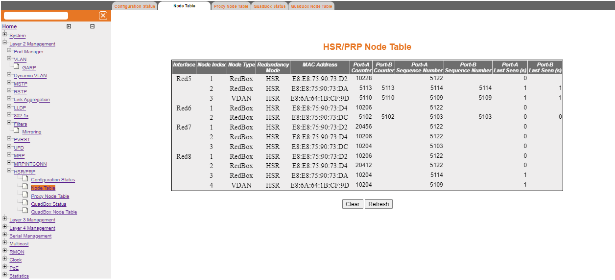
Figure 2. HSR/PRP Interface Status

Screen Objective This screen allows the user to check the HSR/PRP Interface Status. All fields shown below are status fields, which are not configurable.
Navigation

Layer 2 Management > HSR/PRP > Configuration Status

Fields
  • Interface
  • Line Card
  • Node Table Timeout (s)
  • Node Table Count
  • Proxy Node Table Timeout (s)
  • Proxy Node Table Count
  • QuadBox State
  • QuadBox VLAN ID
  • RSTP Root Path Cost
  • Redundancy Version
  • MAC Address
  • Post-I Internal Connection
  • With Admin State
  • MTU
  • Negotiation Mode
  • Duplex
  • Speed (b/s)

Node Table

Figure 3. Node Table


Screen Objective This screen allows the user to check other nodes on the redundant network that are visible to each HSR/PRP RedBox. All fields shown below are status fields, which are not configurable.
Navigation

Layer 2 Management > HSR/PRP > Node Table

Fields
  • Interface
  • Node Index
  • Node Type
  • Redundancy Mode
  • MAC Address
  • Port-A Counter
  • Port-B Counter
  • Port-A Sequence Number
  • Port-B Sequence Number
  • Port-A Last Seen (s)
  • Port-B Last Seen (s)
Buttons
  • Clear—clears the counters.
  • Refresh—refreshes the screen.

Proxy Node Table

Figure 4. Proxy Node Table


Screen Objective This screen allows the user to check the MAC addresses that the RedBoxes represent on the redundant network. All fields shown below are status fields, which are not configurable.
Navigation

Layer 2 Management > HSR/PRP > Proxy Node Table

Fields
  • Interface
  • Node Index
  • MAC Address
Buttons
  • Clear—clears the entries.
  • Refresh—refreshes the screen.

QuadBox Status

Figure 5. HSR QuadBox Status


Screen Objective This screen allows the user to check status of any configured QuadBoxes. All fields shown below are status fields, which are not configurable.
Navigation

Layer 2 Management > HSR/PRP > QuadBox Status

Fields
  • Line Card
  • QuadBox Condition
  • Interface
  • HSR-HSR Mode
  • Interface Admin State
  • Port-A Admin State
  • Port-A Link State
  • Port-B Admin State
  • Port-B Link State
Buttons
  • Refresh—refreshes the screen.

QuadBox Node Table

Figure 6. HSR QuadBox Node Table


Screen Objective This screen allows the user to check the redundant nodes that a configured QuadBox can observe. All fields shown below are status fields, which are not configurable.
Navigation

Layer 2 Management > HSR/PRP > QuadBox Node Table

Fields
  • Interface
  • Node Index
  • Node Type
  • Redundancy Mode
  • MAC Address
  • Port-A Counter
  • Port-B Counter
  • Port-A Sequence Number
  • Port-B Sequence Number
  • Port-A Last Seen (s)
  • Port-B Last Seen (s)
Buttons
  • Clear—clears the settings.
  • Refresh—refreshes the screen.