STP (Spanning-Tree Protocol) is a link management protocol that provides path redundancy while preventing undesirable loops in the network that are created by multiple active paths between stations. To establish path redundancy, STP creates a tree that spans all of the switches in an extended network, forcing redundant paths into a standby or blocked state.
For an Ethernet network to function properly, only one active path should exist between two stations. Multiple active paths between stations in a bridged network can cause loops in which Ethernet frames can endlessly circulate. STP logically breaks such loops and prevents looping traffic from clogging the network. The dynamic control of the topology provides continued network operation in the presence of redundant or unintended looping paths.
- RSTP
- MSTP
- PVRST+
RSTP is a portable implementation of the IEEE 802.1D standard. It provides rapid recovery of connectivity following the failure of a bridge/bridge port or a LAN. It reduces the time to reconfigure the active topology of the network when physical topology or topology configuration parameters changes. It provides increased availability of MAC service when there is a reconfiguration or failure of components in a bridged LAN. It can interoperate with legacy STP bridges without any change in the configuration.
MSTP is a portable implementation of the IEEE 802.1s standard. It is used to configure spanning tree on per VLAN basis or multiple VLANs per spanning tree. It allows you to build several MST over VLAN trunks, and group or associate VLANs to spanning tree instances, so the topology of one instance is independent of the other instance. It provides multiple forwarding paths for data traffic and enables load balancing. It improves the overall network fault tolerance, as failure in one instance does not affect the other instances.
For each VLAN, a spanning-tree instance is created. Number of spanning-tree instances supported in PVRST depends on the number of instances supported by the hardware. PVRST operates only on supported instances
Redundant Ring Technology
The network recovery time is very critical in industrial applications. Industrial networking devices often utilize redundant ring technologies to minimize the downtime. The iMR320 adheres to the implementation of various network protocol standards (STP, MSTP/RSTP/PVRST, MRP, HSR/PRP) to meet the performance criteria of mission critical applications.
STP, MSTP/RSTP/PVRST, and MRP are Ethernet based protocols. HSR is a non-Ethernet layer 2 protocol and on the iMR320 require a dedicated line module. The following table compares these different protocols.
| Redundancy Ring Comparison Table | |||
|---|---|---|---|
| Recovery Technology | RSTP | MRP | HSR |
| Recovery Time | < 200 ms | < 200 ms | 0 |
| Maximum Nodes | 40 | 50 | 512 |
| Recovery Time Per Node | 5 ms | 4 ms | 0 |
| Standard | IEEE 802.1D-2004 | IEC-62439-2-2016 | IEC62439-3 |
PRP (IEC 62439-3) is another redundancy option, however it is not a ring redundancy protocol. Instead PRP sends packets over two different networks in parallel.
HSR Protocol
High-availability Seamless Redundancy (HSR) is similar to Parallel Redundancy Protocol (PRP) but is designed to work in a ring topology. Instead of two parallel independent networks of any technology (LAN-A and LAN-B), HSR defines a ring with traffic in opposite directions.
In HSR, to allow the determining and discarding duplicate frames, additional protocol specific information is sent with the data frame. In HSR, the frames are identical except for the path field in their 6 octet HSR header (tag), both directions around a loop. The idea is that one copy of the message will reach the destination node, even if the loop is broken.
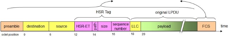
Periodically, so called supervision frames, which allow supervision of the status of the redundant network, e.g. broken links, are sent.
Network devices which do not have the ability to communicate by HSR, can be connected to an HSR ring via a RedBox, i.e. redundancy box. The intended recipient of the redundant copies of the HSR frame passes the first copy of the message up the network stack and discards the second one.
Media Redundancy Protocol
Media Redundancy Protocol (MRP) is a networking protocol designed to implement redundancy and recovery in a ring topology. MRP is designed to react deterministically on a single failure on a switch in the MRP ring.
In an MRP ring, according to IEC 62439-2, one of nodes in the network takes on the role of the media redundancy manager (MRM), and the other nodes are the redundancy clients (MRC). The MRM initiates and controls the ring topology to react to network faults by sending control frames on one ring port over the ring and receiving them from the ring over its other ring ports.
MRM and MRC ring ports support three status: disabled, blocked, and forwarding. Disabled ring ports drop all the received frames. Blocked ring ports drop all the received frames except the MRP control frames. Forwarding ring ports forward all the received frames.
During normal operation, the ring works in the Ring-Closed state. In this state, as a loop prevention, one of the MRM ring ports is blocked, while the other is forwarding. Conversely, both ring ports of all MRCs are forwarding. Loops are avoided because the physical ring topology is reduced to a logical stub topology.
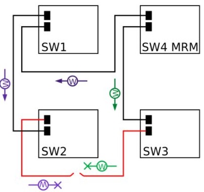
In case of failure, the network works in the Ring-Open state. For instance, in case of failure of a link connecting two MRCs, the MRM sets both of its ring ports to the forwarding state; the MRCs adjacent to the failure have a blocked and a forwarding ring port; the other MRCs have both ring ports forwarding. So, in the Ring-Open status, the network logical topology is a stub.
MRP Rings
The customer will be deploying MRP rings in their substations for fast failover and ease of configuration.
Ring-Closed MRP Ring
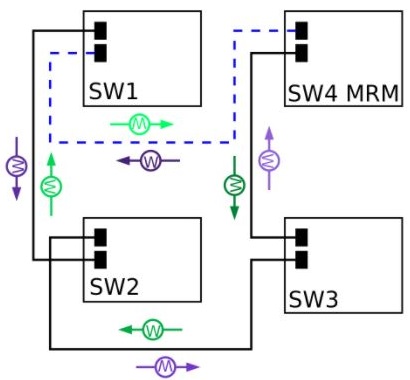
This picture above shows an MRP ring in a closed condition. The MRM switch is the MRP Media Redundancy Manager and it is the designated switch that controls the ring and prevents the network loop from forming. “W” are the watchdog packets that transit the network much like RSTP BPDUs. If there is a line failure, the W frames alert the MRM to put its redundant port to forwarding.
For the blocked port on the MRM, only watchdog frames are allowed to pass, and not data frames.
Ring-Open MRP Ring
The figure below shows the ring in an open state with the MRM engaged.
MRP Ring Size
A ring of 50 switches is currently supported.
Media Redundancy Automanager
To configure a Media Redundancy Automanager (MRA), the node or nodes select an MRM by election and configured priority value.
The MRA role is not an operational MRP role like MRM or MRC. It is only an administrative temporary role at a device startup. A node must transition to the MRM role or the MRC role after startup, and the MRM is selected though the manager voting process.More Information
Detailed Configuration Guides are available at: https://is5com.com/configuration-manuals/