Information Note: Redundant Switch and Main Switch Interaction

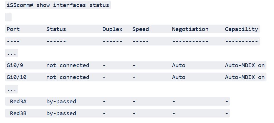
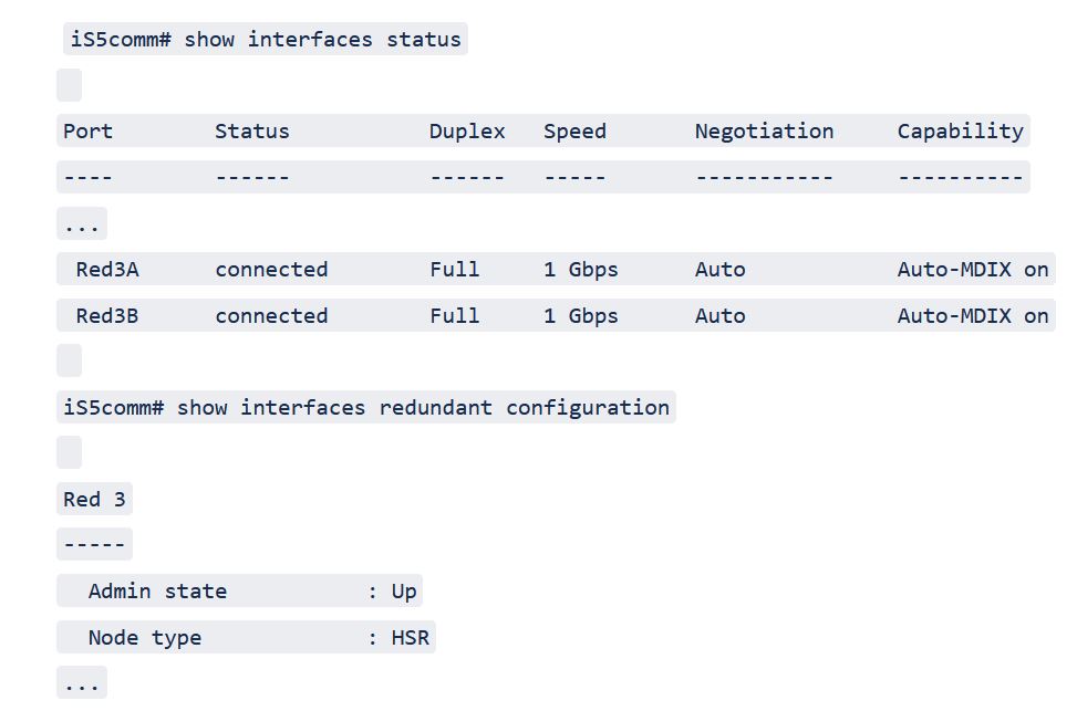
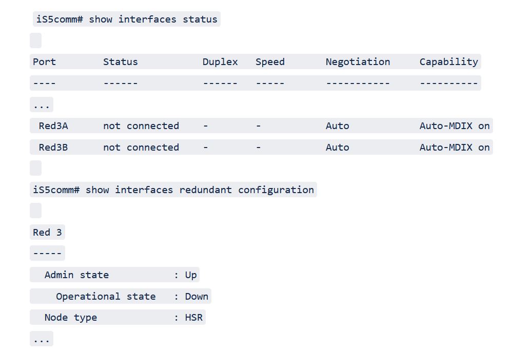
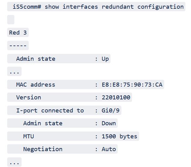
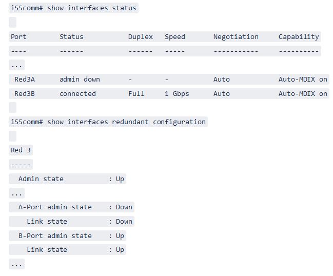
Ethernet ports on the main switch are normally connected directly to a PHY and the port operational status is directly dependent on the PHY state. The redundant switch however has been inserted in the path between the main switch and the PHYs so that when redundancy is enabled (default mode) the main switch Ethernet port is no longer connected to the PHY. When redundancy is disabled the main switch Ethernet ports are connected back to the PHY as with the general setup.

Figure 1. Redundancy Enable and Disable Modes


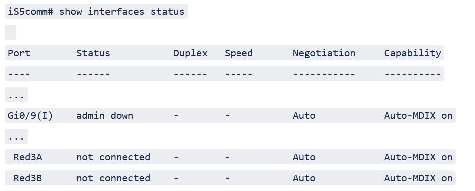
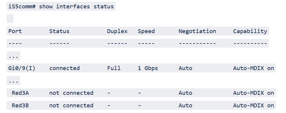
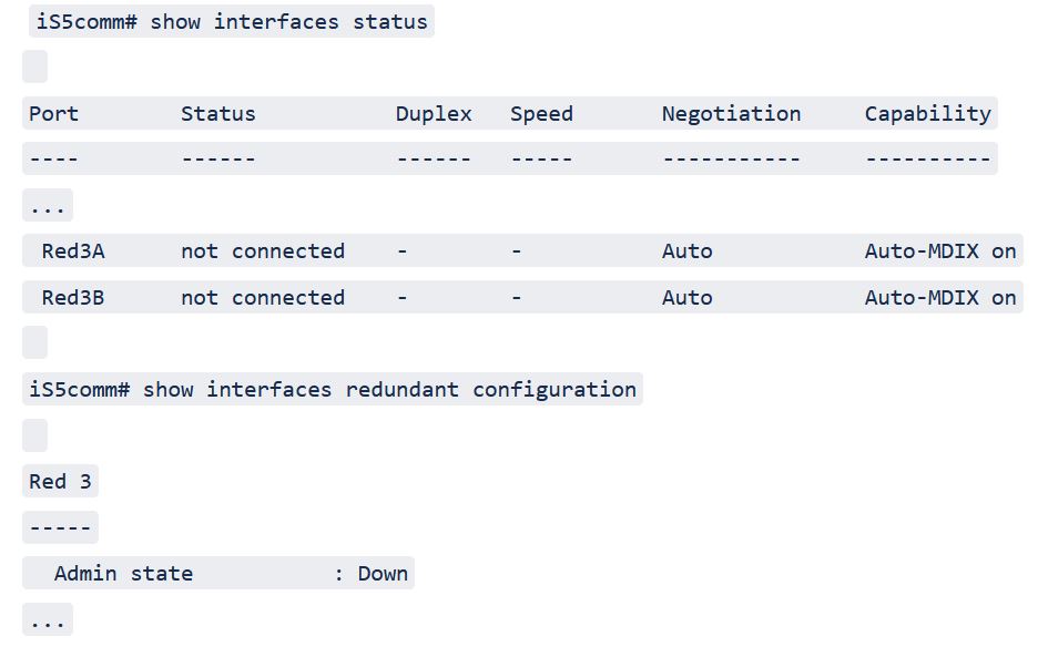
From a control point of view, the redundant interfaces and the Ethernet interfaces operate as independent units because they have their own administrative and operational states that are not linked. The administrative state on both interfaces must be brought up to enable Ethernet traffic to flow between the redundant network and the main switch. This allows the main switch to be disconnected (by bringing only the Ethernet port down) from the redundant network while keeping an HSR ring intact (fully redundant). The redundant interface also has separate administrative states for the Port-A and Port B so that a single connection to the redundant network can be removed.

Command Line Information

The main command to get some general information on the command line is “show interfaces status”. This gives a good indication how each interface/port is operating including link state and administrative state. For redundant interfaces more detailed information can also be obtained with the “show interfaces redundant configuration” command. The HSR/PRP line card defaults to redundant mode, but each redundant interface can be changed to bypass mode with the “redundancy disable” command to provide standard Ethernet connectivity.

Ethernet Interface

An Ethernet Interface can be in redundant or bypass mode.

Redundant Mode

In redundant mode, the main switch Ethernet port is no longer connected directly to the PHY, but internally connected to the Redundant switch. In this mode the status of the Ethernet port can be either
  • “admin down” if in “shutdown” state or
  • “connected” if in “no shutdown” state
irrespective of the administrative state of the redundant interface as it is connected to internal hardware (indicated by the “(I)” after the interface name). This can be displayed with the “show interfaces status” command.

For example, gi 0/9 in “shutdown” state is as shown below.


In another example, gi 0/9 in “no shutdown” state is as shown below.


Bypass Mode

In bypass mode, the Ethernet port is connected to the PHY, so it has
  • “admin down” status in “shutdown” state, and
  • “connected” or “not connected” status in “no shutdown” state
depending on the link state of the PHY.

For example, gi 0/9 in “no shutdown” state with PHY link down in bypass mode is as shown below.


In this case the “(I)” is no longer attached to the name, and the additional port (in this case gi 0/10) also becomes available (the additional port is not available on LM4, and the port is also limited to 1Gb/s).

Redundant Interface

The redundant interface can be in one of three states:
  • redundant mode with “admin down” state (default),
  • redundant mode with “admin up” state,
  • or bypass mode state
It is not possible to change directly form redundant mode with “admin up” state to bypass mode state, instead it is necessary to transition through the default redundant mode with “admin down” state to ensure that redundant or normal Ethernet traffic is shut down before changing.

Redundant Mode

In redundant mode with “admin down” state the redundant switch is disabled so that no Ethernet traffic passes from the main switch to the redundant network. The “redundancy enable” command can be used from the bypass mode state, or “shutdown” command from the redundant mode with “admin up” state to proceed to this state in the redundant interface configuration CLI mode.

For example, redundant interface 3 in redundant mode with “admin down” state is as shown below.


Redundant Mode with “admin up” State

In redundant mode with “admin up” state the redundant switch is enabled with the configure parameters so that Ethernet traffic can passes from the main switch to the redundant network. The “no shutdown” command can be used from redundant mode with “admin down” state to proceed to this state in the redundant interface configuration CLI mode.

For example, redundant interface 3 in redundant mode with “admin up” state is as shown below.


In this state the link status of the A and B port determine the operational status of the redundant interface. At least one of the links must be “connected” for the redundant interface to be operational (default state). If both links are down no traffic will flow between the redundant network and the main switch and the operational state will be down.

For example, redundant interface 3 in redundant mode with “admin up” state with operational state down is as shown below.


Bypass Mode

In the bypass mode state, the main switch Ethernet port is directly connected to the PHY and bypasses the redundant switch. The “redundancy disable” command can be used from redundant mode with “admin down” state to proceed to this state in the redundant interface configuration CLI mode.

For example, redundant interface 3 in bypass mode state is as shown below.


show interfaces redundant link-stats

The “show interfaces redundant link-stats” can be used to check when and how often the links have changed state.

There are some parameters that are shared between the Ethernet interface and the redundant interface so that they only need to be setup once. These parameters include the MAC address, the MTU, and Auto negotiation (both speed and duplex) and can be changed on the Ethernet interface. The parameters are synchronized when either interface is brought up. The Ethernet port administrative state is also displayed if it in the “admin down” state.

For example, redundant interface 3 connection to Ethernet port is as shown below.


The A and B ports can also be brought down with the “port A down” or “port B down” commands in the redundant interface configuration CLI mode for testing purposes.

In another example, the redundant interface 3 with A port down is as shown below.