PTP Devices
For this version of Raptor, PTP supports end-to-end and peer-to-peer transparent clocks.
The other 2 types of clocks are ordinary and boundary transparent clocks. They are explained in this chapter but are NOT supported by this version of Raptor.
Ordinary Clock (not supported at the current version)
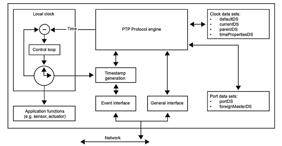
An ordinary clock can be a grandmaster or slave clock in a master-slave hierarchy. Master clocks provide the time reference to other nodes, and slave clocks synchronize to a master clock. The ordinary clock has a single PTP port and single PTP port state. It consists of the local clock, the PTP control engine, the data and port data sets, timestamp functions for event messages, and application functions.
The ordinary clock executes the port state machine and BMC (Best Master Clock) algorithm to select the PTP port state. If the port is in the master state, the local clock is synchronized to an external source of time traceable to TAI (International Atomic Time) and UTC (Universal Coordinated Time) such as GPS (Global Positioning System) system. If the port is in slave state, the local clock is synchronized with its master clock.
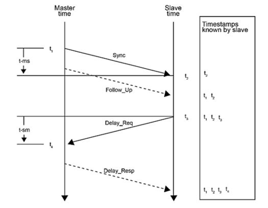
A PTP ordinary clock sends and receives PTP messages to synchronize the clocks. The ordinary clock contains one physical port and two logical interfaces to handle PTP event messages and PTP general messages separately. The PTP event messages are timestamp messages. Ordinary clock can use Delay request-response mechanism or Peer Delay request-response mechanism to calculate the propagation delay. In addition to event messages, general messages are used to transport non-timing critical data between the devices, such as Announce or Follow_Upmessages. PTP ordinary clocks are connected application devices such as sensors or actuators.
Boundary Clock (not supported at the current version)
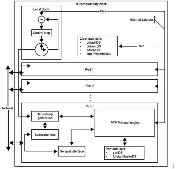
The boundary clock can be grandmaster or master or slave clock in a master-slave hierarchy. It can have more than one port. It has functionally similar to the ordinary clock, except that a boundary clock executes port state machine on each port and BMC algorithm to select the port state of each port. The local clock and clock data set are common for all ports in the boundary clock.
A boundary clock is used only as a network element and is not associated with application devices such as sensors or actuators.
End-to-End Transparent Clocks
End-to-end (E2E) transparent clocks forward PTP messages, measure the residence time of PTP event message at the transparent clock, and add this residence time in the correction field of the PTP messages. Transparent clock timestamps the event messages on ingress and egress port. The difference between these timestamps is the residence time within the transparent clock. E2E transparent clocks will not execute port state machine and BMC algorithm to select the state of the port. E2E transparent clocks may be used as a network element, or they may be associated with application devices such as sensors or actuators if an ordinary clock is combined with the end-to-end transparent clock.
- Configure PTP on global switch level.
- Enable/disable PTP protocol at port level.
- Show the current PTP configuration and statistics
- Go to PTP mode and set mode to E2E Transparent mode or Peer to Peer (P2P) Transparent mode.
- Set the number of ports that can support Transparent mode.
- Set minimum amount of time between sending PDelay request message in P2P mode.
- Save PTP configuration.
- Debug the PTP module.
RC stands for rate estimation and control and RE1—rate estimation relative to master.
Peer-to-Peer Transparent Clocks
The P2P transparent clock differs from the end-to-end transparent clock in the way it corrects and handles the timing messages. The E2E transparent clock time stamps all PTP timing messages; peer-to-peer transparent clock forwards only Sync and Follow up messages.
The P2P transparent clock
- calculates the residence time of PTP messages in peer-to-peer transparent clock
- uses Pdelay Req-Pdelay Resp mechanism to measures the link delay between two ports implementing link delay (the link delay is used to is used to correct timing information in Sync and Follow_Up messages)
- uses rate estimation and control mechanism to avoid the residence time error.
The Peer-to-peer transparent clock use the following event messages:
- Pdelay_Req
- Pdelay_Resp
- Pdelay_Resp_Follow_up
The P2P transparent clock may be used as a network element or it may be associated with application devices such as sensors or actuators if an ordinary clock is combined with the peer-to-peer transparent clock.
Where,
RC stands for rate estimation and control,
RE1—rate estimation relative to master, and
RE2—rate estimation relative to neighbor.
PTP Transparent Clock with Profiles Configuration Summary
- User configures PTP on global switch level.
- With the current configuration, a user configures 4 profiles. User can create PTP domain explicitly (implicitly done by configuring profile).
- User can enable/disable PTP protocol at port level.
- User is able show the current PTP configuration and statistics.
- User can go to PTP mode and can set mode to “E2E Transparent mode” or “P2P Transparent mode”.
- User can set the number of ports that can support Transparent mode.
- User can set minimum amount of time between sending peer delay request message in transparent P2P mode.
- User can save PTP configuration.
- User can debug the PTP module.