Topology for Configuring and Testing OSPF-BFD
Figure 1. OSPF-BFD Configuration and Testing
Topology
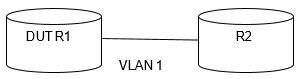
The above shown figure depicts the components used in the topology. The description is as follows:
- R1 and R2 represent the routers.
- VLAN 1 represent the VLAN interfaces of the ISS routers.
- Each ISS switch has a router ID. DUT stands for device under test.
For the list of the IPv4 and IPv6 addresses of the interfaces and hosts provided in the figure above, refer to the table as follows.
| Router | Interface | Slot | IPv4 Address / Mask | IPv6 Address/ Prefix Length |
|---|---|---|---|---|
| R1 | VLAN 1 | 0/2 | 20.0.0.1 / 255.0.0.0 | fe80::201:2ff:fe03:401 2001::2:0:0:1/64 |
| R2 | VLAN 1 | 0/2 | 20.0.0.1 / 255.0.0.0 | fe80::202:2ff:fe03:401 2001::2:0:0:1/64 |