MRP Interconnect

What is MRP Interconnect

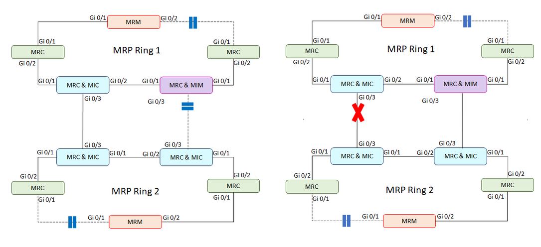
As per IEC 62439-2, it is possible to redundantly interconnect two or more MRP rings via the Media Redundancy Protocol (MRP) Interconnection Protocol. An MRP Interconnection setup consists at a minimum of two rings and two redundant interconnection links between these rings. The redundant interconnection links are provided by four dedicated devices supporting the MRP Interconnection protocol. The roles of these four devices must be one Media Redundancy Interconnection Manager (MIM) and three Media Redundancy Interconnection Clients (MIC). All four devices must additionally take one of the basic operational MRP roles, MRC or MRM, as they are also part of the MRP rings. MRP Interconnect protocol used either of the below two modes to find the failure in the network among these 4 devices.

LC mode and RC mode

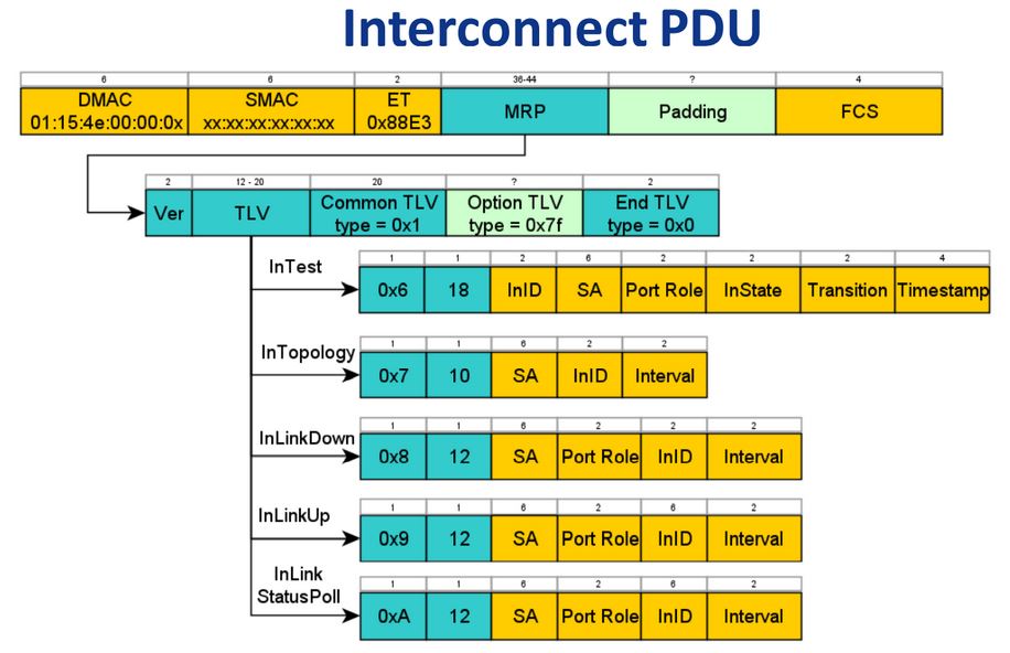
MRP Interconnect has two modes: LC mode (CFM-based) and RC mode (MRP_InTest frames).

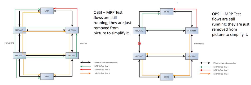
In Ring Check (RC) mode, the MRP Interconnection protocol uses sending and receiving of circling MRP Interconnection test frames (MRP_InTest frames) to derive the interconnection state.

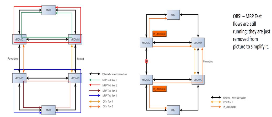
In Link Check (LC) mode, the MRP Interconnection protocol uses link detection mechanisms (e.g. CFM) between coupling devices to derive the interconnection state. LC mode has the advantage of restricting the interconnection test frame load only to the interconnection links, whereas RC mode has the advantage of deloading the MICs from interconnection test frame processing.

The selection of the mode has to be made in accordance with the requirements of the application.

For MRP Interconnect, we support RC mode.

MRP Interconnect Function

The following figure explains the basic functionality of the MRP Interconnection protocol.

Figure 1. Basic Functionality of the MRP Interconnection Protocol


MIM and MIC Port States

Media Redundancy Interconnection Manager (MIM)

The Media Redundancy Interconnection Manager (MIM) shall control its interconnection port state as follows by:
  • Directly reacting only on interconnection port link change notifications from the MICs and from its own interconnection port (LC mode); or
  • Reacting on MRP_InTest frames (RC mode);
  • Setting its interconnection port in BLOCKED state if:
    • it is in LC mode and receives interconnection port link up notifications from its own interconnection port and from the MICs in the interlink connection (this means that the interconnection topology is closed—see the figure above);
    • it is in RC mode and receives its own MRP_InTest frames (this means that the interconnection topology is closed—see the figure above).
  • Setting the interconnection port in FORWARDING state if:
    • it is in LC mode and receives an interconnection port link down notification from at least one of the MICs in the interlink connection (this means that the interconnection topology is open).
    • it is in RC mode and does not receive its own MRP_InTest frames within a configured time according to MRP_IN_TSTdefaultT and MRP_IN_TSTNRmax (this means that the interconnection topology is open).

Synchronization between MIM and MIC

The following mechanism supports synchronization between MIM and MIC during interconnection topology changes.
  1. The MIM shall indicate changes in the interconnection topology state to the MICs, and to the MRMs in the connected MRP rings, by means of MRP_InTopologyChange frames.
  2. When it is in LC mode, the MIM shall, after startup and after recognition of a link up at its interconnection port, issue a MRP_InLinkStatusPoll frame at its ring ports to poll the status of the redundant interlink connection from the MICs.
  3. When it is in RC mode, the MIM shall, after startup and after recognition of a link up at its interconnection port, cyclically send and receive MRP_InTest frames at its ring ports and at its interconnection port to detect the status of the interconnection topology. When a transition to open or close interconnection topology is detected, then the MIM shall send the MRP_InTopologyChange frames through both ring ports and through its interconnection port to the MICs and to the MRMs to initiate the interconnection topology change.
  4. If the MIC receives an MRP_InTopologyChange frame, then the MIC shall, after recognition of a link up at its interconnection port, change the port state of its interconnection port to FORWARDING.
  5. If the MRMs receive a MRP_InTopologyChange frame, then the MRMs shall send MRP_TopologyChange frames at both ring ports, with the delay, after which all MRCs and MICs in the connected MRP rings will clear their Filtering Database (FDB).
  6. The MIM shall not forward its own MRP_InTest frames between the ring ports and its interconnection port. The MIM shall forward MRP_InLinkChange frames, MRP_InLinkStatusPoll frames and MRP_InTopologyChange frames received on one ring port to the other ring port and vice versa.
  7. The MIM shall process MRP_InLinkChange frames and MRP_InTopologyChange frames. The MIM shall not forward MRP_InLinkChange frames, MRP_InLinkStatusPoll frames and MRP_InTopologyChange frames if the MIM received these frames at its interconnection port.
  8. Each MIC shall send the configured delay in MRP_Interval to the MIM in the MRP_InLinkUp and MRP_InLinkDown frames to tell the MIM after which time the MIC will change its interconnection port state from BLOCKED to FORWARDING (MRP_InLinkUp frame) or from FORWARDING to BLOCKED (MRP_InLinkDown frame).
  9. Each MIM shall support BLOCKED port state at the interconnection port.

Media Redundancy Interconnection Client (MIC)

  1. The interconnection port of the MIC shall be connected to the interconnection port of a MIM in another MRP ring, and the interconnection port of another MIC in the same ring shall be connected to the interconnection port of a MIC in this other MRP ring, thereby forming a MRP interconnection topology as shown in the figure above.
  2. Each MIC shall forward MRP_InTest frames received on one ring port to the other ring port and to the interconnection port. Each MIC shall forward MRP_InTest frames received on the interconnection port to both ring ports.
  3. If the MIC detects a failure or recovery of the interconnection port link, the MIC shall notify the change by sending MRP_InLinkChange frames through both of its ring ports. Each MIC shall forward MRP_InLinkChange frames received on one ring port to the other ring port and vice versa.
  4. Each MIC shall forward MRP_InLinkChange frames received on one of the ring ports to the interconnection port. Each MIC shall forward MRP_InTopologyChange frames received on one ring port to the other ring port and vice versa.
  5. Each MIC shall process MRP_InTopologyChange frames. It shall, after recognition of a link up at its interconnection port, change the port state of its interconnection port to FORWARDING.
  6. After receiving a MRP_InLinkStatusPoll frame from the MIM, each MIC shall respond with a MRP_InLinkChange status frame informing about its current interconnection port link status.
  7. Each MIC shall support BLOCKED port state at the interconnection port.

Working Principle of MRP Interconnect Mode in LC Mode

Figure 2. Working Principle of MRP Interconnect mode in LC Mode (Interconnect Close & Open Scenario)


Working Principle of MRP Interconnect mode in RC Mode

Figure 3. Working Principle of MRP Interconnect mode in RC Mode (Interconnect Close & Interconnect Open Scenario)


Roles of MIM, MIC, MRM, and MRC

Figure 4. Roles of MIM, MIC, MRM, and MRC


Default MRP Interconnect Profiles

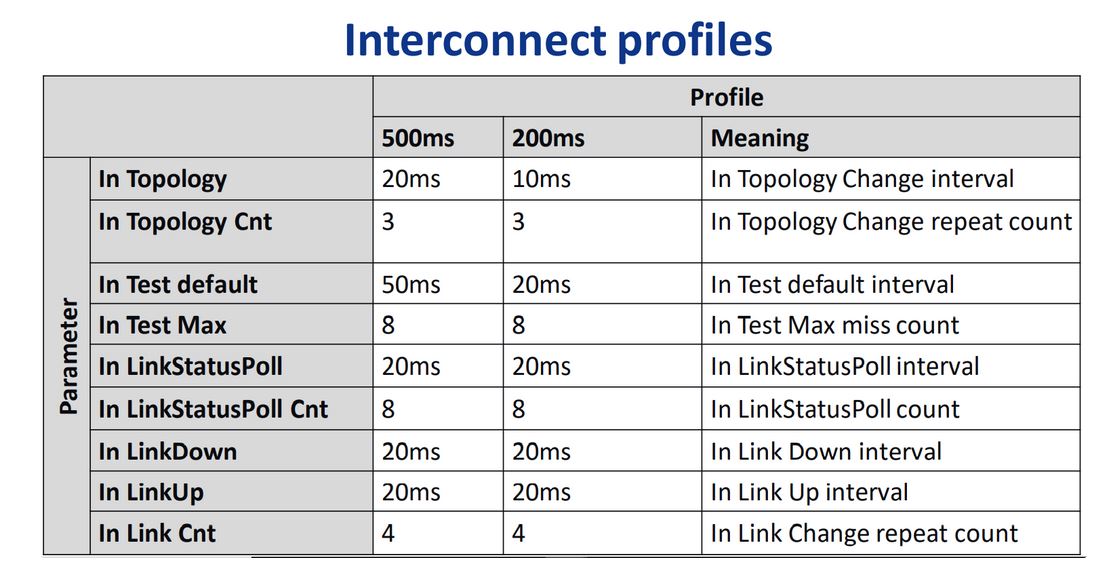
The Default MRP Interconnect Profiles are as follows.
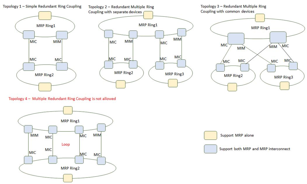
Figure 5. MRP Interconnect Profiles


MRP Interconnect frames

Figure 6. MRP Interconnect PDUs


MRP Interconnect Use Cases

Figure 7. MRP Interconnect Use Cases


Table 1. Topology Description
Topology Number Description
Topology 2 Redundant Multiple Ring Coupling with separate devices, multiple application of MRP Interconnection in one common ring, and other separate rings
Topology 3 Redundant Multiple Ring Coupling with common devices, multiple application of MRP Interconnection in one common ring, and other separate rings
Topology 4 Multiple application of MRP Interconnection in more than one common ring is not allowed. Forwarding links Loops cannot be resolved by MRP Interconnection protocol.
Topology 1 Basic MRP Interconnect functionality of simple redundant ring coupling requires one MIM with 3 MICs to be configured.