MRP Design

Media Redundancy Protocol (MRP) is a networking protocol designed to implement redundancy and recovery in a ring topology, and redundant interconnection of multiple MRP rings. MRP is designed to react deterministically on a single failure of an interswitch link or when switching the MRP ring or interconnection topology.

Redundancy Summary

Redundancy within the network considers the presence of more network elements (switches, link) than necessary operation, in order to prevent the loss of communication caused by a failure. To implement this, there is more than one physical path between 
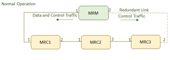
any two nodes. As per the IEC 61918 specified ring topology, every switch has a redundant connection (link) into the network. The redundant 
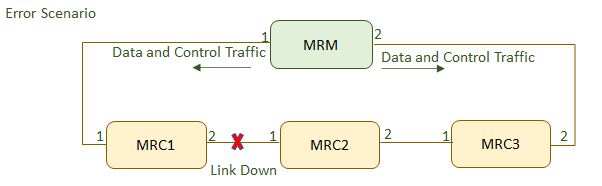
links are not required for a failure-free/normal operation of the network; however, in case of a failure, these redundant links are used to prevent the breakdown of the network. The disadvantage of ring topology is that it can introduce a “packet loop” that creates broadcast storms in the network.

Spanning Tree protocols (STP), such as RSTP, specify a method for providing media redundancy while preventing the undesirable packet loop in a network. (i.e. RSTP was developed to detect and eliminate the physical loop in the network). Also, in case of a failure in the network, a topology change notification is sent out to create a different safe path.

Although STP is effective enough for many networks, it takes longer time for reconvergence in case of failure. This is not good enough for mission-critical industrial Ethernet applications.

To overcome the limitations of RSTP, MRP protocol was developed. MRP uses mechanisms similar to RSTP (e.g., deleting forwarding database after reconfiguration, setting ports into blocking or forwarding mode), but it takes lesser time for reconvergence in case of failure. Shown below is the comparison between MRP and RSTP.

Table 1. Comparison between MRP and RSTP
  MRP RST
Topology Ring Any
Number of switches 50+ Maximum of 40 Switches
Recovery time Recovery time in case of a failure can run into Less than 200ms Recovery time in case of a failure can run into seconds depending on the topology and size of the network.
Configuration Simple Medium

MRP Function

It is the MRM’s responsibility to monitor the ring topology. During normal ring operation (i.e., no link or node failure in the ring topology), the MRM disconnects one of its ring ports, so that the ring topology becomes ‘loop free’ from a communication point of view. As soon as the ring is open due to the failure of a node, and the data communication is broken, the MRM reconfigures the data paths within 200 ms by enabling the disconnected ring port and creating a new loop free topology.

Figure 1. MRP Normal Operation


Figure 2. MRP Error Scenario


MRP Ring Port States

An MRP ring is set up via dedicated ring ports. An MRP Interconnection is set up via dedicated interconnection ports.

By default Ring / Interconnect port can be either linkup/down state. If a ring port or interconnection port is in the state LINK_UP, MRP will modify the port states of the ring and interconnection ports to prevent loops in a ring or interconnection topology.

A ring port or interconnection port may be assigned one of the following states.
  • BLOCKED: indicates that all frames are dropped except:
    • MRP topology change frames and MRP test frames from a MRM,
    • MRP link change frames from an MRC,
    • MRP Interconnection topology change from a MIM,
    • MRP interconnection link change from a MIC, and
    • frames from other protocols that also define to pass blocked(2) ports.
  • FORWARDING: indicates that all frames are passed through according to the forwarding behavior of IEEE 802.1D.
  • DISABLED: indicates that all frames are dropped, but it is not set by MRP though.

MRP Frames

MRP information is sent in the form of an Ethernet frame (MRP Frame) with Type–length–value (TLV) structures, thus allowing organizationally specific information.

MRP messages are always sent to the specific MAC address with the OUI = 00-15-4E and EthType 0x88E3. The following multicast MAC addresses are used for basic MRP and MRP Interconnect.

Table 2. Multicast MAC Addresses used for basic MRP and MRP Interconnect
MAC Purpose
01-15-4E-00-00-01 It is used for monitoring the ring state via test frames.
01-15-4E-00-00-02 It is used to indicate link changes from MRC to other ring members, and to indicate ring topology changes from MRM to all MRC via control frames.
01-15-4E-00-00-03 It is used for monitoring the interconnection state via test frames.
01-15-4E-00-00-04 It is used to indicate link changes from MIC to the MIM, poll the MIC status, and indicate interconnection topology changes from MIM to all MRM via control frames.

As these multicast MAC addresses are not within the port local bridge group address area 01-80-601 C2-00-00-xx defined in [IEEE 802.1Q], received frames with these multicast addresses shall be propagated to all Layer 2 connected ports when MRP is off.

A summary of an MRP frame is shown below.

Table 3. Summary of MRP Frame
PRE SFD DstMac SrcMac EhtType MRP Data PAD FCS
7 bytes 1 byte 6 bytes 6 bytes 2 bytes 46-1500 bytes 4 bytes
    01-15-4E-00-00-01/01-15-4E-00-00-02/01-15-4E-00-00-03/01-15-4E-00-00-04 Port Mac Address 0x88E3      

Normal Operation: Ring Closed

To detect errors in the network, the MRM sends MRP_Test frames on both of its ring ports. These frames run through the ring in both directions until they arrive at the other ring port of the MRM. These MRP_Test frames are marked with a special MAC address and forwarded by the MRCs only to the opposite ring ports. They are sent periodically every MRP_Test default interval (20 ms by default). If the MRP_Test frames come back to both ends of the MRM, the ring is detected as defect-free (ring closed) and the MRM blocks the loop. This is done by changing the state to BLOCKED at one of the ring ports in the MRM and the other as FORWARDING as shown in Figure 2 below. On this BLOCKED port only test frames for supervising the ring (MRP_Test frames) are sent. Data frames are sent by the MRM only on the port in FORWARDING state.

Figure 3. MRP Normal Operation with Traffic Shown


Table 4. MRP Normal Operation
  Ring Port 1 Ring Port 1
MRM Forwarding Blocked
MRC1 Forwarding Forwarding
MRC2 Forwarding Forwarding
MRC3 Forwarding Forwarding
Note:

A blocked port can transmit and receive only the control traffic. Hence, MRM transmit the data traffic only via Ring Port 1.

Failure Detection: Ring Open

If MRP_Test frames (typically 3 frames in sequence) are not received by the MRM, the ring topology is considered as interrupted. So it takes 60 ms to detect a failure in the ring. To change the topology in the whole ring, all MRCs and the MRM have to clear their Filtering Data Base (FDB)s at the same time as the redundant port is changing state from BLOCKED to FORWARDING to keep the network consistent. The MRM sends 3 MRP_TopologyChange messages with 10ms delay into the ring with the indication that the topology has changed. The blocked port on the MRM changes the state from BLOCKING to FORWARDING. Every MRC receiving MRP_TopologyChange indications is supposed to clear its FDB at the MRP_TOPchgT time. Afterwards, MRCs have to build again the FDB based on the new topology.

Figure 4. MRP Failure Detection


Table 5. MRP Normal Operation
  Ring Port 1 Ring Port 1
MRM Forwarding Forwarding
MRC1 Forwarding Link Down
MRC2 Link Down Forwarding
MRC3 Forwarding Forwarding
Note:

The ring is open due to a link fault between MRC1 and MRC2. MRM ports (1 & 2) are in forwarding state and transmit and receive both data and control traffic.

The time between detecting a ring interruption and restoring a new data structure is referred to as the recovery time. The recovery time has a maximum value of 200 ms. As soon as the fault is recovered in the network, the redundancy manager disconnects its ring port again and informs the clients of the change.